100% Original, Ready to Ship!

ABB 89XV01A-E GJR2398300R0100 Fuse Module Installation Guide
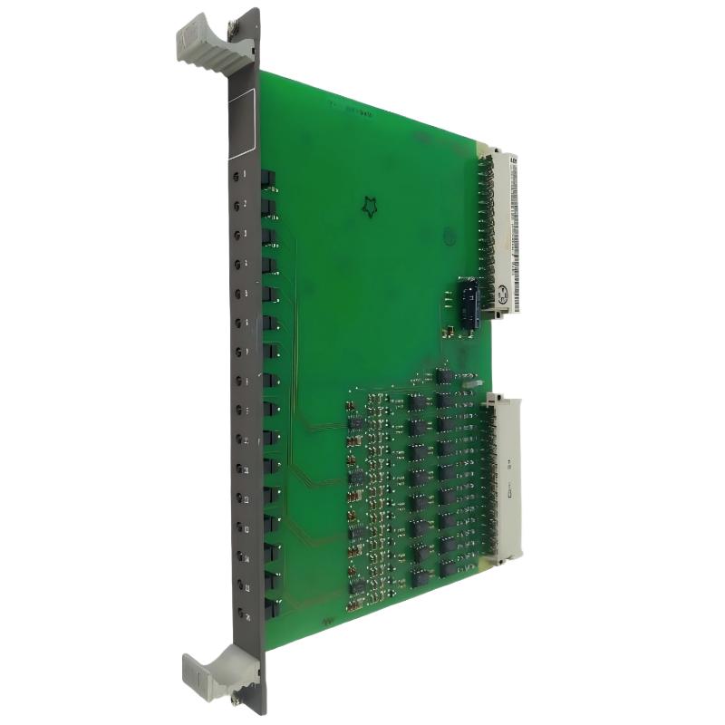
The ABB 89XV01A-E GJR2398300R0100 Fuse Module installation process should begin with verification of the protection circuit, the specified fuse characteristics, and the module’s compatibility with the existing ABB Procontrol system. Incorrect fuse selection, loose connections, or an unsuitable replacement can compromise circuit protection even when the module appears to be installed correctly. This Installation Guide covers practical preparation, mounting checks, Setup, and Commissioning without assuming unverified electrical ratings or terminal assignments.
ABB 89XV01A-E Fuse Module Installation Guide Contents
- Fuse Module Function and Application
- Installation Preparation and Safety
- Module Mounting and Electrical Connections
- Setup and Commissioning Checks
- Field Installation Assessment
- Frequently Asked Questions
- Installation Summary
ABB 89XV01A-E GJR2398300R0100 Fuse Module Function
The ABB 89XV01A-E is identified by industrial spare-parts listings as a fusing module associated with the ABB Procontrol product family. Its intended role is related to electrical circuit protection. The exact protected circuit, fuse arrangement, rated voltage, current capacity, and terminal configuration must be established from the applicable manufacturer documentation and the installed system drawings.
During an installation, engineers should distinguish between a fuse module and an electronic PLC Controller or signal-processing Module. A fuse module does not replace control logic, and its successful installation alone does not demonstrate that the complete System Configuration is ready for operation.
ABB 89XV01A-E Installation Preparation and Safety Checks
Before removing an existing unit or installing a replacement, review the electrical schematic, cabinet layout, equipment identification, and maintenance records. The part number must match the intended application; physical similarity is not sufficient evidence of electrical compatibility.
- Confirm the complete designation: 89XV01A-E and GJR2398300R0100.
- Verify the permitted fuse type, voltage rating, current rating, breaking capacity, and time-current characteristics against the approved documentation.
- Identify the upstream supply, downstream loads, and any associated control or indication circuits.
- Check the module body, fuse holders, terminals, and connector surfaces for cracks, corrosion, discoloration, or heat damage.
- Prepare the correct insulated tools and approved electrical test instruments.
Isolate all relevant energy sources, apply the site’s lockout/tagout procedure, and verify absence of voltage with a properly rated tester. Follow the required test-before-and-after verification practice. A control-system stop command is not an electrical isolation method.
ABB 89XV01A-E Module Mounting and Wiring Verification
Install the fuse module in the designated position and orientation shown in the approved assembly drawing. Do not infer terminal assignments from another ABB module or from connector position alone. If the unit uses a rack, backplane, or dedicated connector, inspect its mating surfaces and confirm that the module is seated correctly before restoring power.
- Compare the replacement unit with the removed module and the approved parts list.
- Check that mounting hardware and retaining mechanisms are intact and correctly secured.
- Inspect each accessible conductor for damaged insulation, loose strands, or signs of overheating.
- Verify the wiring against the actual circuit diagram, including supply and load sides where applicable.
- Tighten terminals only to the torque specified by the applicable manufacturer documentation.
- Check protective earth and cabinet bonding where required by the equipment design.
Never bridge a fuse position with wire or install a fuse with a higher rating simply to prevent repeated interruptions. Such changes can remove the intended protection and expose connected equipment to excessive fault energy.
ABB 89XV01A-E Fuse Module Setup and Commissioning
The Commissioning process should demonstrate that the module is correctly installed and that the protected circuit behaves as expected under the approved test procedure. Do not energize the equipment while wiring discrepancies or unresolved insulation faults remain.
- Visual inspection: Confirm the correct part, fuse specification, seating, and wiring.
- Electrical verification: Perform the continuity, insulation, and other prescribed tests only under conditions appropriate to the circuit and connected electronics.
- Supply verification: Measure the relevant supply voltage at documented test points and compare it with the design specification.
- Controlled energization: Restore power according to the approved commissioning sequence while monitoring the protected circuit.
- Functional confirmation: Verify that the connected equipment operates normally and that no unexpected fuse operation, abnormal heating, or protection alarm occurs.
- Documentation: Record the fitted fuse specification, measurements, replacement details, and test results.
The following pseudocode illustrates a documentation workflow; it is not an ABB controller command and must not be entered into a PLC as executable logic.
IF part_number_matches AND fuse_specification_verified
    THEN proceed_to_approved_electrical_checks
ELSE
    keep_equipment_isolated
    investigate_documentation_and_compatibility
END_IF

IF wiring_verified AND test_results_acceptable
    THEN authorize_controlled_energization
ELSE
    keep_equipment_isolated
    correct_discrepancy
END_IF
ABB 89XV01A-E Installation: Field Assessment Example
Consider a representative maintenance scenario in which a replacement fuse module is installed during a planned shutdown, but the downstream equipment fails to receive power after restart. The first engineering decision should be to avoid immediately condemning the replacement module.
The technician should compare the installed part number with the maintenance record, verify the fuse specification, and inspect the supply and load paths. With the circuit safely isolated, the fuse and associated connections can be examined using the approved procedure. Once the circuit is safe for measurement, voltage checks at designated test points can help distinguish a missing upstream supply from an open fuse or a downstream wiring problem.
This is an illustrative diagnostic scenario, not a verified service report for this exact model. No measured voltage, fuse rating, or repair outcome is claimed. Actual findings must be entered from site measurements rather than estimated to make the commissioning report appear complete.
ABB 89XV01A-E Fuse Module Installation FAQ
Which fuse should be installed in the ABB 89XV01A-E?
Use only the fuse type and ratings specified for the actual circuit and confirmed by the applicable manufacturer documentation. The complete module designation alone does not establish the correct fuse rating.
Can the ABB 89XV01A-E be replaced while the control cabinet is energized?
Do not assume that live replacement is permitted. Isolate the relevant supplies and verify absence of voltage unless explicit manufacturer instructions and an approved site procedure establish otherwise.
Does the ABB 89XV01A-E require PLC software configuration?
A fuse module primarily provides circuit protection rather than programmable logic. Whether associated PLC Controller configuration or alarm checks are necessary depends on the surrounding System Configuration and the circuit design.
What should be checked if the equipment does not restart after installation?
Check the upstream supply, fuse condition, wiring, connector seating, downstream load, and any associated interlocks or protection alarms. Follow the approved circuit diagram and fault-finding procedure.
ABB 89XV01A-E Fuse Module Installation Summary
Reliable installation of the ABB 89XV01A-E GJR2398300R0100 Fuse Module depends on part identification, correct fuse selection, safe electrical isolation, verified connections, and documented commissioning results. Engineers should confirm all model-specific ratings and terminal details from approved technical documentation rather than extrapolating from similar modules. A disciplined Installation Guide and Setup procedure reduces commissioning uncertainty and helps preserve the protection intended by the original system design.
 ABB SS110 3BSE007698R1 Voting Unit Installation Guide
 ABB DX522 1SAP245200R0001 Digital Input/Output Module Installation Guide
 ABB SD823 3BSC610039R1 Power Supply Installation Guide
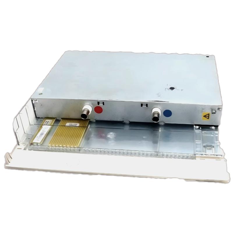 ABB DI685 3BDS005833R1 Digital Input Module Installation Guide