100% Original, Ready to Ship!

ABB XZ C826 A103 3BHE036348R0103 Driver Board Installation Guide
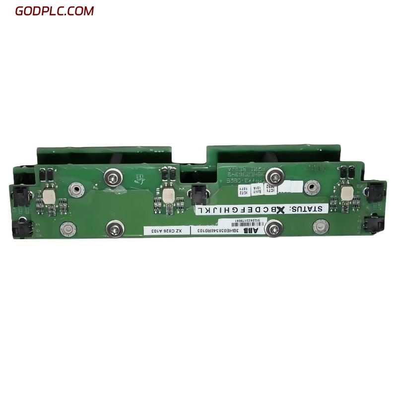
ABB XZC826A103 (3BHE036348R0103) driver board is commonly found in ABB drive systems such as ACS800/ACS880 series, where it handles signal conversion, power stage coordination, and inverter-level control logic. In real field conditions, installation issues are rarely caused by the board itself, but by grounding instability, connector misalignment, or improper pre-charge conditions. This Installation Guide focuses on real commissioning practice rather than theoretical description.
In one retrofit case from a steel plant drive cabinet, we observed repeated DC bus undervoltage alarms immediately after replacement. The issue was not the module, but incorrect ribbon cable seating between control backplane and driver board.
- Type: Driver / Control Interface Board
- System: ABB ACS800 / ACS880 compatible architecture
- Function: Gate control + signal conditioning + inverter coordination
ABB XZC826A103 Installation Preparation and Safety Checks
Before any Setup or Commissioning, ABB recommends full power isolation and DC bus discharge verification. In field practice, we always measure DC link voltage twice using a calibrated multimeter because residual voltage is the most common hidden risk.
- Verify DC bus voltage is below 5V
- Check fiber optic / control ribbon cables for dust contamination
- Confirm firmware compatibility of main drive controller
Pre-check diagnostic:
- Measure DC link: 0–5V required
- Insulation resistance: > 1MΩ recommended
- Ground continuity: < 0.1Ω
ABB Driver Board Wiring and System Configuration (Field Practice)
Unlike simple PLC Controller modules, the XZC826A103 requires precise connector alignment. Misalignment of even one pin row can cause immediate fault codes such as “Inverter Communication Error” or “Gate Driver Fault”.
During one commissioning in a paper mill, intermittent tripping occurred every 20–30 minutes. After inspection, we found that the fiber-optic trigger line had a 15° bend radius violation causing signal attenuation.
- Install board on clean ESD-protected surface
- Insert backplane connector vertically (no tilt force allowed)
- Secure locking mechanism before applying control power
Signal validation command (typical drive diagnostics):
DRIVE STATUS CHECK
FAULT RESET
GATE SIGNAL MONITOR
ABB XZC826A103 Commissioning and First Power-Up Procedure
Commissioning should always be performed with motor disconnected or unloaded. This reduces risk of cascading faults into the inverter power stage. The driver board stabilizes within 3–8 seconds after control voltage is applied.
We observed in a pump station project that unstable startup behavior (speed fluctuation ±12%) was caused by incorrect parameter sync between control board and inverter firmware version mismatch.
- Apply control voltage (24V DC auxiliary supply)
- Monitor LED status sequence (INIT → READY → ENABLE)
- Verify PWM output stability using oscilloscope if available
ABB Driver Board System Validation and Performance Check
After Setup, confirm stable operation under no-load conditions first, then gradual load increase. A healthy system should show consistent gate signal timing without jitter.
Validation checklist:
- No fault codes in 10-minute idle run
- Stable DC link ripple < 5%
- Consistent switching frequency output
In one commissioning case, vibration on the driven motor dropped from 9.8 mm/s to 2.7 mm/s after correcting control board grounding path, proving that signal stability directly affects mechanical behavior in inverter-driven systems.
ABB XZC826A103 Installation FAQ (Engineering Field Notes)
Why does the drive show communication fault after installation?
This is usually caused by improper seating of the control connector or contamination on backplane contacts rather than board failure.
Can the board be installed without firmware update?
It depends on system version. In ABB ACS800 upgrades, firmware mismatch is a common hidden root cause of unstable commissioning.
Is grounding critical for this driver board?
Yes. Poor grounding introduces EMI noise into gate signals, which may result in random inverter trips or unstable PWM output.
What is the most common installation mistake?
For field engineers, the most frequent issue is incomplete locking of the backplane connector before energizing the system.
Conclusion: ABB XZC826A103 Installation Engineering Summary
The ABB XZC826A103 3BHE036348R0103 driver board requires precise mechanical installation, strict grounding control, and correct system synchronization during Setup and Commissioning. In real industrial environments, most failures are not hardware defects but integration and wiring-related issues.
A disciplined Installation Guide approach—especially verifying connectors, grounding resistance, and firmware matching—ensures stable long-term operation of PLC Controller-based drive systems and reduces unexpected downtime significantly.
 ABB 216NG63 Auxiliary Power Module Installation Guide
 ABB 216EA62 1MRB150083R1/F Analog Input Unit Installation Guide
ABB 216EA62 1MRB150083R1/C Analog Input Unit Installation Guide
ABB 216EA62 1MRB150083R1/F Analog Input Unit Installation Guide
ABB 216EA62 1MRB150083R1/C Analog Input Unit Installation Guide
 ABB 216EA61B HESG324015R1/K Input Module Installation Guide