
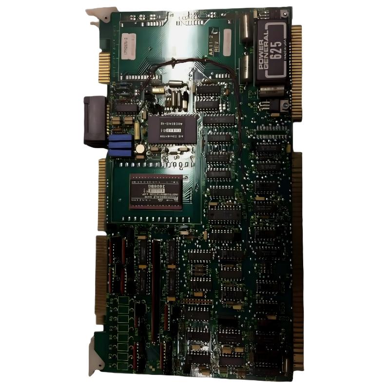
ABB 6101BZ10010A analog input faults should be diagnosed by separating field-signal problems from board-level problems. A missing, unstable, or incorrectly scaled value does not automatically mean the Analog Input Expansion Board has failed. The fastest Troubleshooting method is to compare the physical signal, board-side status, channel configuration, and controller value in sequence.
ABB 6101BZ10010A Analog Input Fault Symptoms
Typical symptoms associated with an analog expansion input include a channel that remains at a fixed value, an input that fluctuates unexpectedly, a signal that disagrees with the field instrument, or a process value that appears reasonable but is assigned to the wrong point.
- Analog channel remains near zero or another fixed value.
- Controller value changes even though the field process is stable.
- One channel is abnormal while neighboring channels operate normally.
- Several channels fail simultaneously.
- Measured field signal is correct but the software value is incorrect.
- Input behavior changes after cabinet work or board replacement.
The number of affected channels is a useful diagnostic clue. One abnormal channel often directs attention toward the field circuit or channel interface. Several channels failing together makes power, common reference, connector, or board-level causes more important.
ABB 6101BZ10010A Fault Diagnosis Logic for Analog Inputs
Good Fault Diagnosis starts with a comparison rather than a component replacement. Establish what the field instrument is producing, then determine whether that information reaches the control system correctly.
Field transmitter
      |
      v
Signal wiring
      |
      v
ABB 6101BZ10010A input interface
      |
      v
Controller / software configuration
      |
      v
Engineering value
If the transmitter output is wrong, investigate the field device. If the transmitter output is correct but the controller value is wrong, investigate wiring, channel assignment, input configuration, or the board interface. This simple separation prevents many unnecessary board replacements.
ABB 6101BZ10010A Analog Signal and Wiring Troubleshooting
For a suspected analog-input fault, begin with the least invasive measurement. Verify the field signal using the appropriate calibrated meter or loop-testing instrument. Avoid disturbing a live process circuit unless the site’s maintenance procedure explicitly permits it.
Field observations should include:
- Actual transmitter output.
- Signal stability over time.
- Continuity and termination condition.
- Shielding and grounding arrangement.
- Connector condition at the expansion board.
- Behavior of adjacent channels.
A noisy signal should not immediately be classified as a defective board. Variable-frequency drives, contactors, motors, poorly routed cables, ground loops, and damaged shielding can introduce interference into low-level analog circuits.
ABB 6101BZ10010A PLC and System Configuration Troubleshooting
When the measured input is correct but the operator display is wrong, move the investigation into the software layer. Check channel mapping, scaling, engineering units, signal inversion where applicable, alarm configuration, and any intermediate logic that modifies the raw input value.
For a replacement board, compare the current System Configuration with the previous working configuration. A hardware replacement can expose configuration discrepancies that were previously hidden by the original installation.
Diagnostic comparison:

MEASURED_FIELD = calibrated_meter_value
RAW_INPUT      = controller_raw_value
DISPLAY_VALUE  = engineering_system_value

IF MEASURED_FIELD is unstable
    investigate field device and wiring
ELSE IF RAW_INPUT is abnormal
    investigate input path and board interface
ELSE IF DISPLAY_VALUE is abnormal
    investigate scaling and application logic
ELSE
    investigate process instrumentation correlation
ABB 6101BZ10010A Analog Input Troubleshooting Case
During a field Troubleshooting investigation, one analog channel showed a value that repeatedly jumped while the associated process transmitter appeared stable. The first inspection found no obvious damage on the expansion board, and the fault did not occur on every channel.
The engineering team measured the field loop directly and observed a stable signal around 16.4 mA. The controller-side value, however, fluctuated significantly. Because the field signal was stable, replacing the transmitter was ruled out.
The investigation then moved toward the cable route and termination. The analog cable was found running close to a high-current switching conductor over part of the cabinet route, and the shielding termination differed from the adjacent instrumentation circuits. After correcting the routing and restoring the approved shielding arrangement, the input trend became stable.
This case demonstrates why Fault Diagnosis should follow the signal path. A board can be blamed because it is the visible automation component, while the actual problem may be electromagnetic interference or installation practice.
ABB 6101BZ10010A Repair and Replacement Decision
Repair should be considered only after external causes have been eliminated. Before removing an ABB 6101BZ10010A from service, compare its behavior with known-good channels and verify that the field signal and System Configuration are correct.
- Confirm the fault is repeatable.
- Record the affected channel and measured signal.
- Compare the channel with a known-good input where practical.
- Inspect connectors and associated wiring.
- Verify the configured channel and scaling.
- Review available system diagnostics.
- Replace the board only when evidence points to the board or its interface.
For legacy industrial control equipment, component-level PCB repair should normally be performed by an appropriately equipped electronics service facility rather than improvised on an operating plant floor. ESD handling, inspection, controlled testing, and post-repair validation are important because an apparently repaired analog circuit may still introduce offset, noise, or drift.
ABB 6101BZ10010A Troubleshooting and Fault Diagnosis FAQ
Does an incorrect analog value prove that the ABB 6101BZ10010A has failed?
No. Wiring, transmitter output, grounding, electromagnetic interference, channel mapping, and software scaling can all produce an incorrect value while the board remains functional.
What does it mean if several ABB 6101BZ10010A input channels fail together?
Several simultaneous failures should direct the investigation toward common power, reference, connector, interface, or board-level conditions before individual transmitters are replaced.
Why is measuring the field signal important during ABB 6101BZ10010A Troubleshooting?
It separates an instrumentation problem from an input-interface problem. Without this measurement, technicians can easily replace an input board when the actual fault is located in the transmitter or cable circuit.
When should an ABB 6101BZ10010A board be replaced?
Replacement becomes reasonable when the external signal is proven correct, configuration is verified, connections are sound, and the affected channel or board shows behavior inconsistent with known-good hardware.
ABB 6101BZ10010A Fault Diagnosis General Overview
Effective ABB 6101BZ10010A Troubleshooting depends on evidence-based isolation of the signal path. The strongest field approach is to verify the transmitter, wiring, board interface, raw controller value, and engineering interpretation separately. This method reduces unnecessary hardware replacement and provides a more reliable basis for deciding whether the Analog Input Expansion Board requires further testing, repair, or replacement.



