
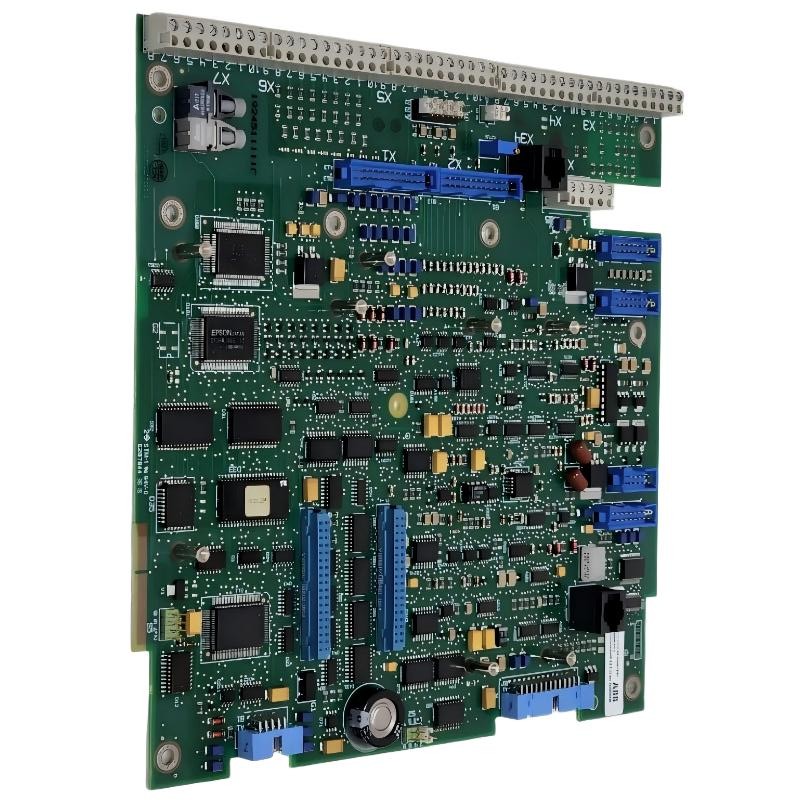
ABB 70SG01R1 DCS System Test Button Unit Troubleshooting Guide
ABB 70SG01R1 DCS System Test Button Unit faults should be diagnosed by tracing the complete signal path rather than immediately replacing the button. A failed test indication can originate from the 70SG01R1, field wiring, terminal connections, control voltage, receiving input, or DCS logic.
ABB 70SG01R1 DCS Fault Symptoms and Signal Behavior
Typical symptoms include no response after pressing the test button, intermittent operation, an unexpected DCS indication, or a signal that remains permanently active. These symptoms have different diagnostic directions.
- No DCS response when the button is operated.
- Intermittent test signal.
- Signal remains active after releasing the button.
- Local circuit response differs from the DCS indication.
- Unexpected alarm or diagnostic status during testing.
ABB 70SG01R1 Fault Diagnosis Through Signal Tracing
A practical Troubleshooting method is to divide the circuit into sections: mechanical device, local wiring, terminal interface, receiving input, and DCS application logic. This prevents a system-level software problem from being incorrectly diagnosed as a hardware failure.
Observe DCS input status
        |
Check control voltage
        |
Test local circuit continuity
        |
Inspect terminal connections
        |
Verify receiving input
        |
Review DCS logic/configuration
Measurements should always be compared with the electrical design values for the specific installation. Do not apply a generic voltage value when the project documentation specifies another control voltage.
ABB 70SG01R1 Troubleshooting: Separating Wiring Faults from Hardware Faults
One useful engineering rule is to prove the external circuit before condemning the 70SG01R1. If the control circuit behaves correctly at the appropriate terminals but the DCS input does not change, the investigation should move downstream toward the input channel or configuration.
If the expected electrical response is absent directly at the unit, inspect the button contacts, conductors, terminals, and control supply. This diagnostic separation can significantly reduce unnecessary component replacement.
ABB 70SG01R1 DCS System Fault Case Analysis
In one field troubleshooting case, operators reported that the DCS test function worked only intermittently. The first observation was that the indication disappeared when the cabinet wiring was lightly disturbed. Rather than replacing the test button immediately, the engineer checked continuity while operating the device and then inspected the terminal block.
The measured circuit behavior pointed toward an unstable connection rather than a permanent device failure. After the affected termination was corrected, repeated operation produced a stable signal. The important Fault Diagnosis lesson was that the physical symptom was associated with the wiring interface, not necessarily the 70SG01R1 itself.
ABB 70SG01R1 Repair and Corrective Action
Repair decisions should follow the evidence collected during Troubleshooting. Loose conductors should be correctly reterminated, damaged wiring should be repaired according to site standards, and a defective test unit should only be replaced after the external circuit has been verified.
- Place the affected control circuit in a safe maintenance condition.
- Record the original symptom before disturbing the wiring.
- Verify the control supply against the approved documentation.
- Check continuity and terminal integrity.
- Verify the receiving DCS input.
- Review the relevant System Configuration and logic.
- Repair or replace the defective component when evidence supports the conclusion.
- Repeat functional testing after corrective work.
ABB 70SG01R1 Post-Repair Commissioning Check
After corrective action, perform multiple test operations rather than accepting a single successful response. Observe the local circuit and DCS indication together. Intermittent faults can remain hidden if the device is tested only once.
- Operate the test button repeatedly.
- Confirm consistent signal transitions.
- Check that the DCS indication returns to its normal state.
- Inspect the repaired termination after testing.
- Record the final diagnostic result in the maintenance documentation.
ABB 70SG01R1 Troubleshooting FAQ
What is the first check when the ABB 70SG01R1 gives no DCS response?
Start by verifying the control circuit condition and expected signal path. Check the applicable control voltage, wiring continuity, terminal connections, and receiving input before replacing the unit.
How can a wiring problem be distinguished from a 70SG01R1 hardware fault?
Test the circuit at defined points in accordance with the schematic. If the expected electrical response is present at the unit but absent at the receiving input, investigate the downstream wiring or input interface.
Why can an intermittent 70SG01R1 fault be difficult to locate?
An intermittent condition may disappear when the cabinet is stationary. Repeated operation, continuity testing, and careful inspection of terminals can help reveal unstable connections.
Should the DCS configuration be checked during hardware troubleshooting?
Yes. A correct physical signal can still produce an incorrect operator indication if the input assignment, logic, or System Configuration does not match the intended circuit.
When should the ABB 70SG01R1 be replaced?
Replacement is appropriate when the unit is confirmed to be defective after the external supply, wiring, terminals, and receiving circuit have been verified.
ABB 70SG01R1 DCS Fault Diagnosis General Overview
Effective ABB 70SG01R1 Troubleshooting depends on evidence-based signal tracing. Checking the control circuit, wiring, terminals, receiving input, and DCS System Configuration in sequence helps distinguish a genuine hardware fault from an installation or interface problem and provides a more reliable basis for repair.



