100% Original, Ready to Ship!

ABB 89XV01A-E GJR2398300R0100 Fuse Module Troubleshooting Guide

ABB 89XV01A-E GJR2398300R0100 Fuse Module faults should be investigated by determining whether the interruption originates in the fuse itself, the upstream power supply, the downstream load, or a connection problem. Replacing a blown fuse without identifying why it operated can lead to repeated shutdowns and possible equipment damage. This Troubleshooting Guide explains a practical Fault Diagnosis approach for maintenance engineers working with ABB Procontrol-related industrial control equipment.
ABB 89XV01A-E Fuse Module Troubleshooting Contents
- Recognizing Fuse Module Fault Patterns
- Fault Diagnosis and Measurement Logic
- Common Causes of ABB 89XV01A-E Fuse Faults
- Corrective Maintenance and Repair
- Fault Investigation Example
- Troubleshooting FAQ
- Fault Diagnosis Summary
ABB 89XV01A-E Fuse Module Fault Symptoms
The most useful initial observation is the relationship between the failure and the operating event. A fuse that opens immediately at energization suggests a different fault pattern from one that opens only after a motor, actuator, or other downstream load starts. Neither pattern proves a particular root cause, but both help narrow the investigation.
- No downstream power: Possible causes include an open fuse, missing input supply, loose connection, or an interrupted downstream path.
- Repeated fuse operation: Investigate short circuits, overloads, incorrect fuse characteristics, wiring errors, and load-starting conditions.
- Intermittent equipment shutdown: Inspect connections, vibration-related contact problems, thermal damage, and changing load conditions.
- Abnormal heating or discoloration: Consider excessive current, high contact resistance, unsuitable connections, or inadequate heat dissipation.
- Protection alarm after restart: Determine whether the alarm reflects an electrical fault, an associated interlock, or a separate control-system condition.
A fuse module should not be diagnosed solely from a PLC alarm. An alarm may identify the affected process or power branch without identifying the failed component.
ABB 89XV01A-E Fault Diagnosis: Trace the Electrical Path
A practical Fault Diagnosis process follows the circuit from its source to the affected load. Begin by reviewing the latest trip or shutdown record, then compare the event with the circuit diagram. Determine whether the fault occurred during initial energization, steady operation, or a load transition.
- Establish the failure boundary. Identify which devices have lost power and which remain operational. This helps distinguish a branch-circuit fault from a broader supply failure.
- Review the event sequence. Record the time of the trip, the equipment state, and any relevant alarms or recent maintenance changes.
- Inspect the de-energized circuit. Under the approved isolation procedure, examine the fuse, terminals, connectors, wiring insulation, and downstream equipment.
- Test the suspected path. Use appropriate instruments and manufacturer-approved methods to assess fuse continuity and wiring integrity. Disconnect sensitive electronics where required before insulation testing.
- Verify supply conditions. If the procedure permits, qualified personnel can measure voltage at designated test points to locate where the supply is lost.
- Confirm the root cause. Establish why the fuse operated or the circuit lost continuity before installing a replacement.
For resistance or continuity testing, isolate the circuit and verify that it is de-energized. Never use an ohmmeter on a live circuit. Live voltage and current measurements must follow the approved electrical safety procedure and use suitably rated instruments.
Common Causes of ABB 89XV01A-E Fuse Module Faults
Fuse operation is evidence that the protection path has interrupted current, not proof that the fuse module itself is defective. The following causes should be considered in context.
- Downstream short circuit: Damaged insulation, conductive contamination, or a failed load may create a low-impedance fault.
- Overload condition: Current may exceed the permitted operating range because of a failing device or an unexpected load increase.
- Incorrect fuse selection: An unsuitable current rating, voltage rating, breaking capacity, or time-current characteristic can cause unsafe or unreliable protection.
- High-resistance connection: Loose or deteriorated contacts can produce localized heating and intermittent voltage loss.
- Supply abnormality: The upstream source or associated distribution equipment may be responsible for the observed failure.
- Incorrect replacement or wiring: A visually similar part or incorrectly reconnected conductor can disrupt the intended circuit.
The correct response is to test each plausible cause against measured evidence. Repeatedly replacing the fuse without investigating the load can hide the original problem and extend downtime.
ABB 89XV01A-E Fuse Module Repair and Recovery
Repair should restore the specified protection characteristics, not merely restore power temporarily. If the fuse has operated, first investigate the downstream circuit and confirm that the fault has been removed. If the module body, holder, or contact surfaces show heat damage, determine whether the affected assembly is approved for repair or must be replaced.
- Replace a failed fuse only with an approved type and rating.
- Correct damaged wiring and defective terminations using approved materials and procedures.
- Replace a module that is cracked, carbonized, mechanically damaged, or otherwise outside its permitted service condition.
- Do not bypass the fuse, increase its rating without authorization, or modify the protection circuit to suppress recurring trips.
- After repair, perform the required continuity, insulation, connection, and functional checks appropriate to the equipment design.
- Restore power under controlled conditions and monitor the circuit for recurring faults.
ABB 89XV01A-E repair decisions must also consider the surrounding System Configuration. If the fuse module is part of a larger control power distribution assembly, verify the effect on associated PLC Controller hardware, interface equipment, indication circuits, and connected loads before returning the system to service.
ABB 89XV01A-E Troubleshooting: An Illustrative Fault Investigation
Consider a representative case in which a control cabinet operates normally after a shutdown but loses power to one branch shortly after the equipment starts. The initial symptom could suggest a faulty fuse, yet replacing the fuse immediately would not establish why the interruption occurred.
The engineer first reviews the circuit drawing and identifies the devices supplied by the affected branch. With the circuit isolated, the fuse and wiring are inspected for signs of damage. The load is then assessed using the approved procedure to determine whether a short circuit or abnormal current demand exists. If the wiring and load pass the required checks, the investigation continues toward the supply source and connection points.
For example, a measured voltage of 0 V downstream of an open protective element would be consistent with an interrupted supply path, but it would not by itself prove that the fuse was the original cause. Measurements on both sides of the protection device, taken at approved test points under appropriate conditions, may help localize the interruption.
This scenario illustrates engineering reasoning rather than a documented repair of a specific ABB 89XV01A-E installation. Actual voltage, current, resistance, and time values must come from the equipment’s approved limits and recorded field measurements.
ABB 89XV01A-E Troubleshooting Logic for Maintenance Records
The following pseudocode shows how findings can be organized in a maintenance checklist. It is conceptual logic, not executable ABB PLC code, and does not authorize energization.
IF downstream_supply_missing
    inspect_upstream_supply
    inspect_fuse_and_connections
    verify_downstream_load
END_IF

IF fuse_open
    investigate_overcurrent_or_short_circuit
    verify_approved_fuse_specification
END_IF

IF heat_damage_detected
    isolate_equipment
    assess_module_and_terminal_condition
END_IF

IF root_cause_corrected AND required_tests_passed
    request_authorized_return_to_service
ELSE
    maintain_isolation
    continue_fault_investigation
END_IF
ABB 89XV01A-E Fuse Module Troubleshooting FAQ
Why does the ABB 89XV01A-E fuse keep blowing?
Repeated fuse operation can result from a downstream short circuit, overload, incorrect fuse selection, wiring problems, or abnormal load-starting conditions. Investigate the cause before fitting another fuse.
How can a technician determine whether the fuse or the module has failed?
Follow the approved isolation procedure and inspect the fuse and holder. Use the specified continuity checks and examine the contacts for heat or mechanical damage. A failed fuse does not automatically mean the complete module must be replaced.
Can a larger fuse rating solve a recurring fault?
No. Increasing the fuse rating without an approved engineering assessment can compromise conductor and equipment protection. Verify the original design specification and correct the underlying fault.
Will a fuse module fault always trigger a PLC alarm?
No. Alarm availability depends on the circuit design and whether the affected power path has monitoring or feedback. A loss of downstream power may occur without a dedicated PLC diagnostic message.
When should the ABB 89XV01A-E be replaced rather than repaired?
Replacement may be necessary when the module has significant heat damage, cracked insulation, damaged contacts, or a defect that cannot be corrected using an approved service procedure. Confirm compatibility before installing a replacement.
ABB 89XV01A-E Fault Diagnosis Summary
Effective troubleshooting of the ABB 89XV01A-E GJR2398300R0100 Fuse Module requires more than checking whether a fuse is open. Engineers should trace the supply path, assess the protected load, verify fuse specifications, inspect connections, and document the measurements that support the final diagnosis. Corrective action should address the underlying electrical condition before the system is returned to operation.
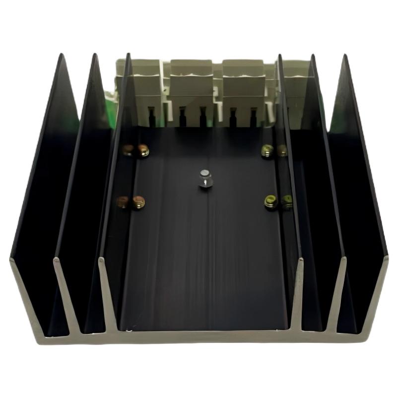 ABB SS110 3BSE007698R1 Voting Unit Troubleshooting Guide
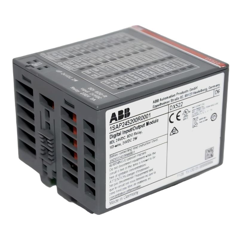 ABB DX522 1SAP245200R0001 Digital I/O Module Troubleshooting Guide
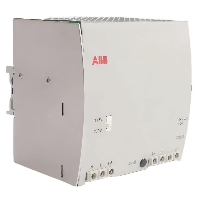 ABB SD823 3BSC610039R1 Power Supply Troubleshooting Guide
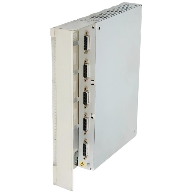 ABB DI685 3BDS005833R1 Digital Input Module Troubleshooting Guide