100% Original, Ready to Ship!

ABB XV D825 A01 3BHE015619R0001 Interface Board Installation Guide
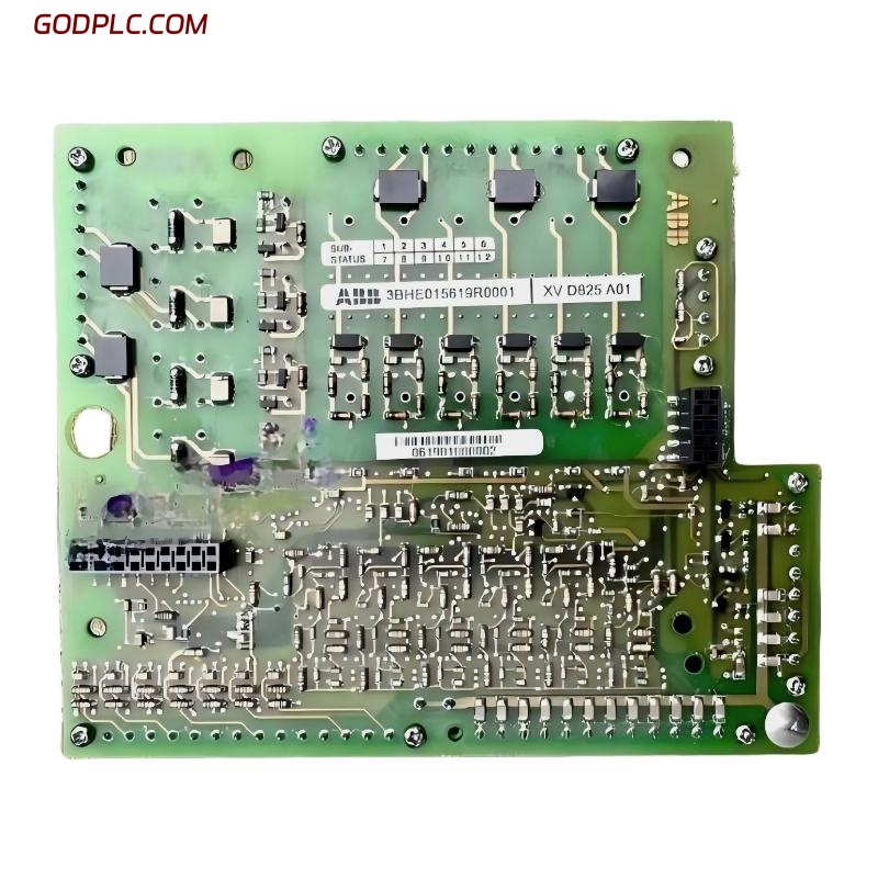
Table of Contents
- ABB XV D825 A01 Interface Board Overview
- Pre-Installation Preparation and Safety
- Mechanical Installation and System Integration
- Signal Wiring and Interface Configuration
- Commissioning and System Validation
- Real Field Installation Case
- FAQ
- Final Engineering Notes
ABB XV D825 A01 Interface Board Overview
ABB XV D825 A01 3BHE015619R0001 interface board installation issues are usually not caused by hardware defects, but by incorrect signal mapping or grounding mismatch inside ABB drive control systems. This board acts as a communication and signal interface layer between PLC controllers, drive electronics, and field I/O in industrial automation environments.
In ACS/drive-based architectures, the ABB XV D825 A01 interface board is responsible for handling mixed signal routing (digital, analog, and fieldbus communication). A wrong installation sequence may lead to unstable PLC controller synchronization, intermittent I/O loss, or full drive communication failure.
Pre-Installation Preparation and Safety
Before performing any Installation Guide procedure for ABB XV D825 A01, engineers must ensure full system isolation. Unlike low-voltage PLC modules, this interface board often sits inside drive cabinets where residual voltage and EMI interference are present.
- Confirm drive DC bus is fully discharged (below 50V)
- Verify control power is isolated from main inverter section
- Use antistatic wrist strap before handling PCB
- Check cabinet grounding resistance (< 1Ω recommended)
- Inspect connector pins for oxidation or mechanical damage
In one commissioning site (cement plant drive room), improper discharge caused residual 320V DC on the cabinet rail even after shutdown. The issue was a failed discharge resistor, not the interface board itself.
Mechanical Installation and System Integration
The ABB XV D825 A01 interface board must be installed with attention to mechanical vibration and signal isolation layout. Incorrect mounting tension or misaligned connector insertion is a common field failure point.
Installation Logic Used in Field Practice
- Align board with guide rails before insertion
- Ensure connector seating without force pressure
- Lock mechanical fixation points gradually (not fully tightened at once)
- Check board flatness against mounting backplane
We observed in one steel plant installation that excessive screw torque caused micro-cracks in solder joints. The system initially worked, but failed after 48 hours due to thermal expansion stress.
Signal Wiring and Interface Configuration
Correct System Configuration is critical when integrating ABB XV D825 A01 with PLC Controller or drive communication modules. Most failures occur due to improper shielding or incorrect fieldbus routing rather than wiring absence.
Recommended Wiring Practices
- Separate analog and digital signal cables
- Use twisted shielded pairs for communication lines
- Ground shield at one end only (control cabinet side)
- Avoid routing parallel to inverter output cables
- Maintain minimum 200 mm distance from power lines
Incorrect shielding behavior often introduces noise spikes. In a packaging machine line, we measured 8–12V induced noise on analog channels due to cable bundling with motor output lines. After rerouting, noise dropped below 0.5V immediately.
Commissioning and System Validation
ABB XV D825 A01 commissioning should always be performed in staged logic rather than full system energization. This prevents cascading faults in PLC communication layers.
Recommended Commissioning Flow
- Step 1: Power control section only (no load)
- Step 2: Verify I/O response in PLC Controller
- Step 3: Check fieldbus handshake stability
- Step 4: Simulate analog input signals
- Step 5: Enable drive interaction mode
During one wastewater treatment plant commissioning, PLC communication dropped intermittently during Step 4. Diagnosis showed incorrect Modbus termination resistor setting rather than board failure.
Real Field Installation Case
A mining conveyor system using ABB drive architecture experienced unstable PLC communication after replacing an old interface board with ABB XV D825 A01. Initial assumption was compatibility failure.
However, troubleshooting revealed:
- PLC Controller was stable under standalone test
- Interface board power supply was correct (24VDC stable)
- Communication failed only during motor start
Root cause analysis showed improper grounding topology. The cabinet had dual grounding paths creating loop current during high load switching. After correcting grounding layout:
- Communication stability improved to 100%
- PLC scan errors disappeared
- Motor start sequence became stable
FAQ
Why does ABB XV D825 A01 lose communication during motor startup?
This is usually caused by EMI interference or grounding loop currents rather than board failure. Motor startup generates high transient noise that affects signal integrity.
Can ABB XV D825 A01 be replaced without reconfiguration?
Not always. Some systems require parameter mapping verification in PLC Controller after replacement.
What is the most common installation mistake?
Incorrect shield grounding and routing communication cables alongside power cables are the most frequent field issues.
Why does analog signal fluctuate after installation?
Ground potential difference or improper shielding termination typically causes unstable analog readings.
Should the board be replaced if PLC does not detect it?
No. Engineers should first verify power supply, connector seating, and communication bus termination.
What happens if connector insertion is misaligned?
It may cause intermittent I/O failure or damage to backplane pins over time.
Final Engineering Notes
ABB XV D825 A01 3BHE015619R0001 interface board installation reliability depends heavily on grounding integrity, signal isolation, and correct system configuration within PLC Controller or drive communication architecture. In most real industrial cases, faults attributed to the board are actually caused by EMI, wiring topology, or commissioning sequence errors. Proper Installation Guide execution significantly improves long-term system stability and reduces unnecessary replacement costs.
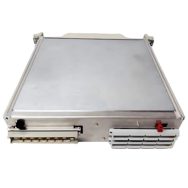 ABB 216NG63 Auxiliary Power Module Installation Guide
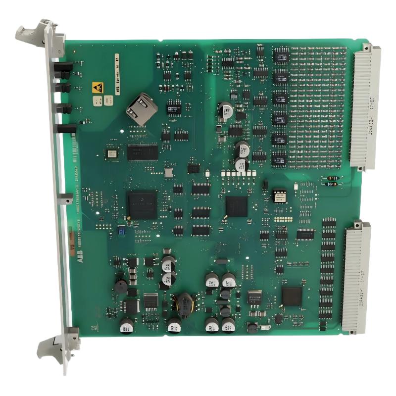 ABB 216EA62 1MRB150083R1/F Analog Input Unit Installation Guide
ABB 216EA62 1MRB150083R1/C Analog Input Unit Installation Guide
ABB 216EA62 1MRB150083R1/F Analog Input Unit Installation Guide
ABB 216EA62 1MRB150083R1/C Analog Input Unit Installation Guide
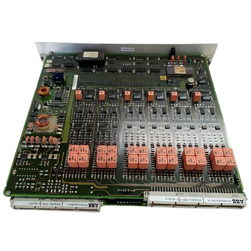 ABB 216EA61B HESG324015R1/K Input Module Installation Guide