
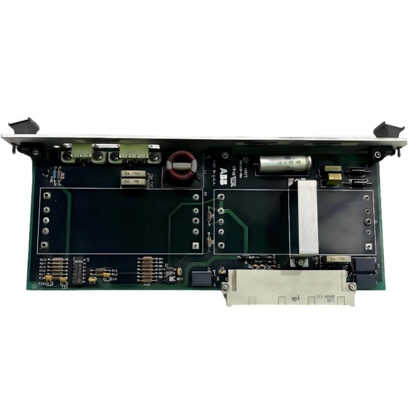
ABB 086369-001 Harmonic Detection Module faults are often caused by abnormal signal conditions, unstable power supply, or incorrect System Configuration. This Troubleshooting Guide explains how engineers perform Fault Diagnosis on ABB 086369-001 modules in industrial environments.
Instead of immediately replacing the PLC Controller Module or control board, experienced technicians normally analyze the complete signal chain, including input power, communication status, grounding condition, and harmonic feedback values.
ABB 086369-001 Harmonic Detection Module Fault Symptoms
- Incorrect harmonic measurement values
- Drive system alarms related to power quality
- Unstable feedback signals
- Module communication interruption
- Controller unable to detect the module
ABB 086369-001 Fault Thinking Process for Engineers
A practical Fault Diagnosis process starts from observation rather than replacement. Engineers normally ask three questions:
- Is the power supply stable?
- Is the signal path correct?
- Is the module receiving valid system information?
In one maintenance case, an ABB 086369-001 Module generated incorrect harmonic feedback. The initial assumption was module damage. However, signal analysis showed the input waveform distortion was caused by a damaged shielding connection. After cable replacement, the measured harmonic feedback dropped from abnormal fluctuation of 18% to a stable range below 3%.
Common Causes of ABB 086369-001 Harmonic Detection Module Fault
- EMI interference from nearby power cables
- Poor grounding connection
- Incorrect System Configuration parameters
- Loose module connector
- Unstable control power supply
- Aging interface components
ABB 086369-001 Troubleshooting Diagnostics Procedure
A professional troubleshooting sequence should separate electrical problems from hardware problems.
- Inspect physical installation condition.
- Measure supply voltage stability.
- Check communication feedback.
- Compare actual harmonic signals.
- Test module replacement only after verification.
ABB 086369-001 Diagnostic Command Example
DISPLAY MODULE STATUS
CHECK INPUT SIGNAL
READ FAULT MEMORY
MONITOR HARMONIC VALUE
VERIFY CONTROLLER LINK
ABB 086369-001 Harmonic Detection Module Repair and Recovery Method
Repair decisions should be based on measurement results. If the module has no power response, technicians should first confirm external conditions before sending the unit for repair.
- Clean and reseat connectors
- Restore correct grounding
- Replace damaged signal cables
- Reload System Configuration parameters
- Replace module if internal circuit failure is confirmed
ABB 086369-001 Real Field Failure Case Analysis
A production line experienced repeated harmonic alarms after a control cabinet upgrade. Engineers measured the ABB 086369-001 input voltage and found unstable DC supply fluctuation from 23.8V to 21.5V. After replacing the aging power supply and improving cabinet grounding, the alarm disappeared during a 72-hour continuous operation test.
ABB 086369-001 Harmonic Detection Module Troubleshooting FAQ
Why does ABB 086369-001 show incorrect harmonic values?
Incorrect readings are commonly related to signal interference, grounding problems, or configuration errors rather than immediate module failure.
Should ABB 086369-001 be replaced when a fault occurs?
Engineers should complete Fault Diagnosis first. Many field failures are caused by external wiring or power conditions.
What tools are useful for ABB 086369-001 troubleshooting?
Multimeters, signal analyzers, configuration software, and system monitoring tools are commonly used during troubleshooting.
ABB 086369-001 Harmonic Detection Module General Overview
The ABB 086369-001 Troubleshooting Guide shows that effective repair depends on engineering analysis rather than simple component replacement. A complete Fault Diagnosis process should include signal inspection, power verification, grounding analysis, and System Configuration checking to achieve reliable PLC Controller and industrial drive operation.



