
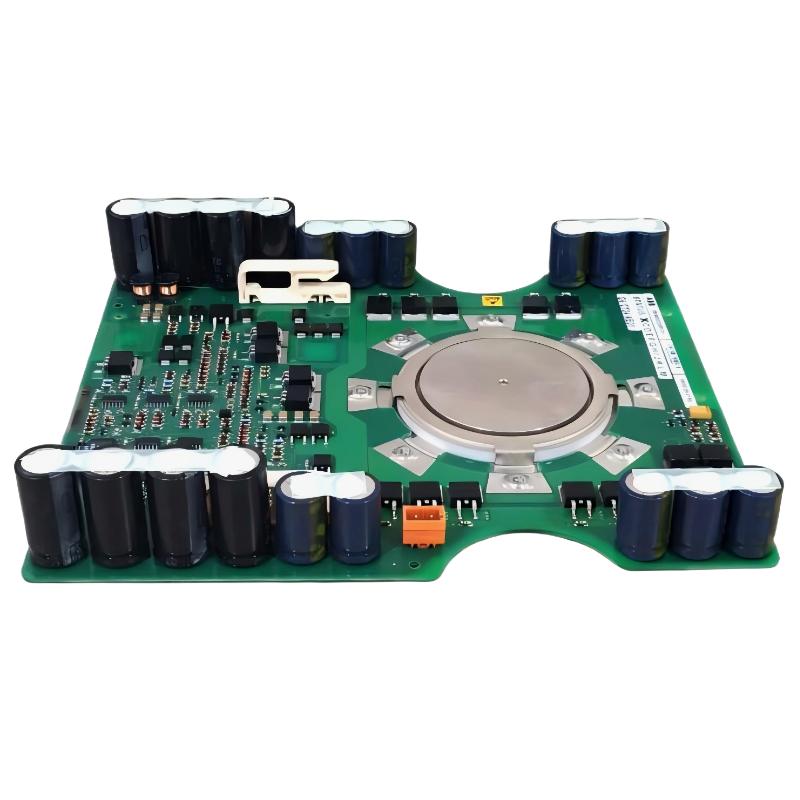
ABB 5SHX1445H0001 IGCT Module Fault Symptoms
ABB 5SHX1445H0001 faults should not be diagnosed by replacing the IGCT immediately. In a medium-voltage drive, an IGCT-related alarm can originate from the gate-drive circuit, fiber-optic communication, cooling system, current feedback, protection logic, or the semiconductor itself. Effective Troubleshooting starts by separating a control-side fault from a genuine power-device failure.
ABB 5SHX1445H0001 Fault Diagnosis Logic
The first engineering question is not “Is the IGCT damaged?” but “At which layer did the failure occur?” Divide the investigation into four areas: power semiconductor, gate-drive circuit, feedback and communication, and external operating conditions.
- Power layer: IGCT, bus connections, stack insulation and switching path.
- Gate layer: gate unit, firing circuit, auxiliary supply and associated connections.
- Feedback layer: current, voltage, temperature and gate-status feedback.
- System layer: controller logic, protection settings and System Configuration.
This approach prevents a common maintenance mistake: replacing an expensive power semiconductor when the original problem is actually a signal or auxiliary-supply fault.
Common Causes of ABB 5SHX1445H0001 IGCT Fault
- Incorrect or unstable gate-drive supply.
- Damaged or poorly seated fiber-optic communication connections.
- Abnormal cooling or insufficient heat transfer.
- Loose power-stack connections.
- Incorrect System Configuration after maintenance.
- Abnormal current or voltage feedback.
- Electrical overstress caused by an upstream converter fault.
- Actual semiconductor damage following a high-energy switching event.
The 3BHL000391P0101 product identification and 5SHX1445H0001 type designation should be checked against the installed spare before concluding that a replacement is correct. Related identifiers such as 5SXE05-0152 can appear in documentation for associated assemblies, so engineers should verify the complete assembly configuration rather than matching one number in isolation.
ABB 5SHX1445H0001 Electrical and Signal Measurements
Measurements should be taken progressively. Start with low-energy control-side observations before attempting any high-voltage investigation. The exact permissible test points and limits must be taken from the relevant ABB equipment documentation.
| Diagnostic Area | What to Observe | Engineering Interpretation |
|---|---|---|
| Gate-drive supply | Stable auxiliary voltage | Unstable supply can create false IGCT faults |
| Fiber-optic feedback | Stable communication/status | Intermittent feedback points toward the signal path |
| Cooling feedback | Normal temperature/flow indication | Abnormal cooling can trigger protection |
| Current feedback | Expected phase relationship | Large imbalance requires further investigation |
Do not use generic voltage or resistance limits from unrelated semiconductor modules. IGCT troubleshooting must follow the electrical class and test procedure of the installed ABB system.
ABB 5SHX1445H0001 Diagnostic Command Sequence
Where the drive’s service interface supports diagnostic commands or status queries, a structured sequence can reduce unnecessary component replacement.
READ DRIVE_STATUS
READ POWER_STAGE_STATUS
READ GATE_DRIVE_STATUS
READ COOLING_STATUS
READ CURRENT_FEEDBACK
READ DC_LINK_STATUS
READ ACTIVE_FAULTS
READ FAULT_HISTORY
COMPARE CHANNEL_STATUS
These are pseudo commands for diagnostic logic, not guaranteed literal commands for every ABB drive platform. The objective is to establish whether the fault follows the power device, the gate-drive channel, or the system feedback path.
ABB 5SHX1445H0001 Repair and Recovery Strategy
If the diagnostic evidence points toward the gate-drive or communication layer, repair that layer before replacing the IGCT. Inspect connector seating, fiber-optic routing, auxiliary power, protection feedback, and configuration parameters.
If there is evidence of semiconductor damage, the repair decision should include the original failure mechanism. Replacing the IGCT without identifying the cause can result in a second failure after restart.
- Record the original alarm and fault history.
- Determine whether the alarm appears immediately or only under load.
- Check control-side and gate-drive diagnostics.
- Verify cooling and feedback signals.
- Inspect the power-stack installation.
- Perform approved electrical tests.
- Replace the affected component only after the evidence supports replacement.
- Repeat Setup and Commissioning checks after repair.
ABB 5SHX1445H0001 Real-World Troubleshooting Case
In one field troubleshooting case, an ABB medium-voltage drive produced a power-stage alarm immediately during startup after maintenance work. The first assumption was that the 5SHX1445H0001 IGCT Module had failed.
The troubleshooting team compared the fault timing with the previous maintenance record. The alarm occurred before meaningful motor loading, which made a load-dependent thermal failure less likely. Gate-drive status was then checked, followed by the feedback path. The semiconductor was not replaced at this stage.
The investigation found an intermittent signal connection associated with the gate-drive communication path. After the connection was corrected and the routing secured, the diagnostic status became stable during repeated startup tests.
The lesson from this case is important: the time at which an ABB 5SHX1445H0001 fault appears is diagnostic information. A fault that occurs immediately during the enable sequence should be investigated differently from a fault that appears after several minutes of high-current operation.
ABB 5SHX1445H0001 Fault Pattern Analysis
Fault timing can provide a useful first filter:
- Fault immediately at enable: investigate gate-drive supply, communication, feedback, and System Configuration.
- Fault during acceleration: investigate current feedback, switching conditions, DC-link behavior, and protection thresholds.
- Fault after extended operation: investigate thermal performance, cooling, mechanical contact, and load conditions.
- Repeated hardware damage: investigate the upstream electrical cause before installing another IGCT.
This fault-thinking process is more reliable than treating every power-stage alarm as an identical Troubleshooting problem.
ABB 5SHX1445H0001 Troubleshooting FAQ
Does an ABB 5SHX1445H0001 fault always mean the IGCT module is damaged?
No. Gate-drive problems, communication faults, cooling alarms, feedback errors, and configuration problems can all produce power-stage-related diagnostics.
What is the first check after an IGCT-related startup alarm?
Record the exact diagnostic message and determine when the alarm occurs. Then inspect gate-drive status, auxiliary supply, feedback communication, cooling status, and System Configuration before condemning the semiconductor.
Can a multimeter alone confirm an IGCT failure?
A basic multimeter may provide useful preliminary information, but it cannot replace the approved semiconductor and power-stack test procedure. High-voltage IGCT systems require controlled diagnostic methods.
Why should the original fault history be saved before repair?
Fault history helps establish whether the problem is instantaneous, load-dependent, thermal, intermittent, or related to a previous maintenance event. This information can significantly narrow the Fault Diagnosis process.
What should be checked after replacing the 5SHX1445H0001?
Repeat the complete installation inspection, gate-drive verification, cooling checks, feedback validation, System Configuration review, and controlled Commissioning sequence before returning the drive to normal service.
ABB 5SHX1445H0001 Fault Diagnosis Conclusion and General Overview
Effective ABB 5SHX1445H0001 Troubleshooting depends on evidence rather than assumptions. The IGCT should be considered one part of a larger medium-voltage power-conversion system. By separating semiconductor, gate-drive, feedback, cooling, and controller problems, engineers can reduce unnecessary replacements and identify the actual root cause. For Repair work, the final objective is not simply to clear the alarm but to confirm stable operation through controlled Commissioning and repeatable diagnostic results.



