
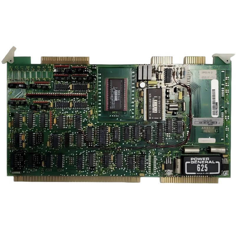
ABB 6100BZ10010B Analog Input Fault Diagnosis Approach
ABB 6100BZ10010B analog input faults should be diagnosed by separating field-signal problems from wiring, configuration, and hardware problems. A channel reading zero, drifting unexpectedly, or disagreeing with a transmitter does not by itself prove that the Analog Input Expansion Board has failed.
ABB 6100BZ10010B Analog Input Fault Symptoms
Different symptoms point toward different sections of the signal chain. A completely inactive channel requires a different investigation from a channel that fluctuates by a few percent or displays a stable but incorrect engineering value.
- Zero or near-zero input: investigate loop continuity, transmitter supply, polarity, and channel wiring.
- Constant incorrect value: investigate scaling, signal range, channel assignment, and reference connections.
- Random fluctuation: investigate shielding, grounding, EMI, loose terminals, and unstable field instrumentation.
- Several channels affected: investigate common power, reference, configuration, or system-level causes.
- Only one channel affected: investigate the individual field circuit before replacing the complete module.
ABB 6100BZ10010B Signal Chain Troubleshooting
A practical Troubleshooting method is to work from the process toward the PLC. Start with the field instrument and progressively move toward the controller. This prevents configuration assumptions from hiding a physical wiring problem.
- Confirm that the field instrument is powered and operating normally.
- Measure the output signal with an appropriate calibrated instrument.
- Measure the same signal at the ABB 6100BZ10010B input terminals.
- Compare the measured signal with the PLC diagnostic value.
- Check channel configuration and application scaling.
- Compare the affected channel with a known-good channel of the same system.
For example, if a transmitter output is measured at approximately 16.0 mA but the PLC diagnostic value does not change accordingly, the investigation should move toward the cable, terminals, input channel, and System Configuration.
ABB 6100BZ10010B PLC Diagnostic Logic
During Fault Diagnosis, record measurements before making configuration changes. A simple diagnostic record can contain the field output, terminal measurement, PLC raw value, engineering value, and diagnostic status.
READ CHANNEL STATUS
READ RAW INPUT VALUE
MEASURE FIELD SIGNAL
MEASURE MODULE TERMINAL SIGNAL
COMPARE WITH KNOWN-GOOD CHANNEL
CHECK SYSTEM CONFIGURATION
CHECK APPLICATION SCALING
The purpose of this sequence is isolation. If the field and terminal signals are correct but the PLC value is abnormal, configuration or input-channel behavior becomes more important. If the signal is already abnormal before reaching the module, replacing the Analog Input Expansion Board is unlikely to solve the problem.
ABB 6100BZ10010B Root Cause Investigation Case
Consider a commissioning fault in which one analog process value repeatedly moved between approximately 7.8 and 8.6 mA while the transmitter indication remained stable. The PLC trend showed the same fluctuation, so the initial suspicion was an unstable analog input.
The investigation did not immediately replace the board. A meter was connected at the transmitter and showed a stable signal. The measurement was then repeated at the control-panel termination point, where the signal showed intermittent variation. Inspection found that the signal termination was not mechanically secure.
After correcting the termination and rechecking the cable route, the input became stable. The lesson from this Troubleshooting case is that an unstable PLC value can originate anywhere in the signal path. The board should be treated as one component of the measurement chain, not automatically as the root cause.
ABB 6100BZ10010B Fault Recovery and Verification
Once the suspected cause has been corrected, recovery should include more than confirming that the displayed value looks normal. The channel should be observed under different operating conditions and compared against the expected process response.
- Confirm stable electrical input under normal operating conditions.
- Check that the PLC diagnostic status is clear.
- Verify the application engineering value.
- Compare the affected channel with independent process measurements where available.
- Monitor the signal trend for intermittent noise or drift.
- Document the root cause and corrective action for future maintenance.
If the same channel repeatedly fails while external wiring and configuration have been proven correct, controlled substitution or further hardware-level investigation may be justified according to the site’s maintenance procedure.
ABB 6100BZ10010B Troubleshooting FAQ
What is the first check for an ABB 6100BZ10010B analog input fault?
Confirm the actual field signal with a suitable measurement instrument before assuming that the expansion board is defective.
Why does an ABB 6100BZ10010B channel show a stable but incorrect value?
A stable incorrect value can result from incorrect signal-range configuration, channel assignment, reference wiring, or application scaling.
What causes fluctuating analog values during ABB 6100BZ10010B Troubleshooting?
Common possibilities include electromagnetic interference, poor shielding or grounding, loose terminations, unstable transmitters, damaged cables, and intermittent connections.
How can a technician distinguish a wiring fault from an input-board fault?
Measure the signal at several points in the signal chain. If the expected signal does not reach the module terminals, investigate the field circuit and wiring before replacing hardware.
Should the ABB 6100BZ10010B be replaced when one channel reads zero?
No. Check transmitter power, loop continuity, polarity, terminal connections, configuration, and diagnostic status first. A single zero channel does not establish a board failure.
How does System Configuration affect ABB 6100BZ10010B Fault Diagnosis?
Incorrect module definitions, channel assignments, signal types, or scaling parameters can produce incorrect PLC values even when the physical input signal is correct.
What indicates that several analog channels may have a common problem?
When multiple channels fail or drift simultaneously, investigate common references, power supplies, configuration, grounding, and system-level connections before focusing on individual channels.
What should be recorded after an ABB 6100BZ10010B repair?
Record the original symptom, measured field signal, terminal measurement, PLC value, identified root cause, corrective action, and final verification result. This creates useful maintenance history for future Fault Diagnosis.
ABB 6100BZ10010B General Troubleshooting Summary
Effective ABB 6100BZ10010B Troubleshooting depends on measured evidence rather than assumptions. Start with the physical signal, trace it through the wiring and input terminals, verify PLC diagnostics and System Configuration, and only then evaluate the hardware itself. This Fault Diagnosis approach reduces unnecessary board replacement and provides a repeatable method for resolving analog input problems during commissioning and plant operation.



