
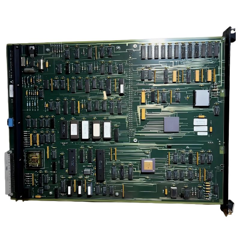
ABB 6205BZ10000G Numeric Input Module Troubleshooting Guide
ABB 6205BZ10000G Numeric Input Module faults should be diagnosed by tracing the signal from the field device to the PLC data table. A channel showing an incorrect value does not by itself prove that the module has failed. Wiring, reference connections, channel configuration, electrical noise, and PLC logic can all create similar symptoms.
ABB 6205BZ10000G PLC Fault Symptoms
Field engineers normally encounter several recognizable patterns when troubleshooting a Numeric Input Module:
- All input channels remain inactive.
- One channel remains permanently active or inactive.
- The displayed input changes intermittently.
- A signal appears on the wrong PLC channel.
- The field device changes state but the PLC value does not.
- The PLC reports an I/O configuration or communication diagnostic.
The pattern is more useful than the alarm message alone. For example, a single abnormal channel generally leads the investigation toward the field circuit, while simultaneous failure across the entire module points toward power, communication, configuration, or common-reference problems.
ABB 6205BZ10000G Fault Diagnosis by Signal Path
Use the following diagnostic sequence conceptually rather than immediately removing the module:
FIELD DEVICE
     |
     v
FIELD WIRING
     |
     v
6205BZ10000G INPUT CHANNEL
     |
     v
I/O STATION
     |
     v
PLC DATA TABLE
     |
     v
APPLICATION LOGIC
This approach helps distinguish a physical input fault from a software interpretation problem. The most useful measurement is usually the comparison between the expected field state and the actual value received by the controller.
ABB 6205BZ10000G Numeric Input Module Diagnostic Measurements
Measurement results should be recorded before any component is replaced. Depending on the specific installation, useful checks can include field signal state, reference potential, continuity, terminal condition, module status, and PLC input data.
- Measure the field signal at the source.
- Compare the signal at the cabinet termination.
- Check whether the same state reaches the assigned input channel.
- Compare the module channel indication with the PLC data table.
- Check for abnormal differences between neighboring channels.
For example, if the field device is confirmed active but the cabinet-side signal is absent, replacing the ABB module will not correct the problem. The fault is upstream of the I/O channel.
ABB 6205BZ10000G Troubleshooting Logic for Intermittent Inputs
Intermittent faults require a different diagnostic mindset. A channel that works for several hours and then changes state should not automatically be classified as a defective module.
In one field investigation, an input was observed switching between its expected state and an inactive state during motor operation. The engineer initially suspected the Numeric Input Module because the PLC diagnostic appeared normal. A comparison of the event timestamp with nearby equipment operation showed that the abnormal input occurred only when a high-power motor started.
The investigation then moved toward cable routing, shielding, grounding, and termination quality. After the affected signal cable was separated from the high-power route and the termination was corrected, the intermittent condition disappeared during repeated motor-start tests.
ABB 6205BZ10000G Common Fault Causes
- Incorrect field termination.
- Loose or oxidized terminal connections.
- Incorrect channel addressing in the PLC.
- Incorrect System Configuration.
- Missing or unsuitable signal reference.
- Electrical noise or EMI coupling.
- Damaged field cable.
- Incorrect application logic interpreting the input data.
- I/O station or controller communication problems.
ABB 6205BZ10000G Module Repair and Recovery Strategy
Repair decisions should follow evidence. If the field signal and wiring are correct but the corresponding input channel consistently fails while equivalent channels operate normally, module-level investigation becomes more reasonable.
Before replacing the module, preserve the diagnostic information. Record the affected channel, field condition, PLC value, station status, and relevant alarm history. This creates a useful baseline for post-replacement verification.
- Record the original fault condition.
- Verify the field device independently.
- Check wiring and reference connections.
- Verify PLC channel configuration.
- Compare the affected channel with a known-good channel where technically appropriate.
- Only then consider module replacement or qualified repair.
- Repeat the complete signal-path test after recovery.
ABB 6205BZ10000G Troubleshooting Diagnostic Commands
Exact commands depend on the host PLC and engineering environment. The following pseudo commands illustrate the diagnostic logic rather than a vendor-specific programming syntax.
READ_IO_STATUS 6205BZ10000G
READ_CHANNEL_STATUS CH01
READ_PLC_INPUT CH01
COMPARE_FIELD_STATE CH01
CHECK_IO_CONFIGURATION
CHECK_STATION_DIAGNOSTICS
The important point is to compare independent observations. A PLC value alone is not sufficient evidence for hardware failure.
ABB 6205BZ10000G Fault Diagnosis Decision Points
If every channel fails simultaneously, investigate common power, station communication, configuration, and reference conditions first. If only one channel fails, concentrate on that channel’s field circuit and termination. If the PLC receives a value but the application displays something different, move the investigation into PLC logic and data handling.
This decision process prevents unnecessary module replacement and reduces commissioning downtime. In field work, identifying where the signal disappears is usually more productive than repeatedly resetting the controller.
ABB 6205BZ10000G Troubleshooting FAQ
Why does an ABB 6205BZ10000G input remain unchanged?
Check the field device, wiring continuity, reference connection, channel status, and PLC configuration. If the field condition changes but the PLC value does not, trace the signal progressively toward the controller.
Can electrical interference cause ABB 6205BZ10000G input faults?
Yes. Depending on the installation, EMI can produce unstable or unexpected input behavior. Cable routing, shielding, grounding, and separation from high-power conductors should be investigated when faults correlate with motor or switching activity.
What does it mean if only one input channel is abnormal?
A single-channel fault generally warrants inspection of that channel’s field wiring, terminal condition, signal source, and configuration before assuming a complete module failure.
When should an ABB 6205BZ10000G module be replaced?
Replacement becomes more justified when the external signal path, wiring, configuration, and controller-side diagnostics have been verified and the same channel continues to behave abnormally under controlled testing.
How should an ABB 6205BZ10000G fault be verified after repair?
Repeat the complete signal-path test from the field device through the I/O channel to the PLC application. Test normal operation as well as the operating condition that originally triggered the fault.
ABB 6205BZ10000G Troubleshooting Guide Conclusion
Effective ABB 6205BZ10000G Fault Diagnosis depends on evidence rather than assumptions. A Numeric Input Module should be treated as one part of the complete control signal chain. By comparing field conditions, electrical measurements, I/O status, System Configuration, and PLC data, engineers can distinguish wiring faults from configuration problems and genuine module failures with much greater confidence.
General Note: Diagnostic procedures, electrical measurements, replacement decisions, and repair work must follow the applicable ABB documentation, plant safety procedures, and the actual I/O system design. Do not apply or measure signals outside their specified electrical limits.



