100% Original, Ready to Ship!

ABB 70EA02A-ES HESG447308R1 Input Module Troubleshooting Guide
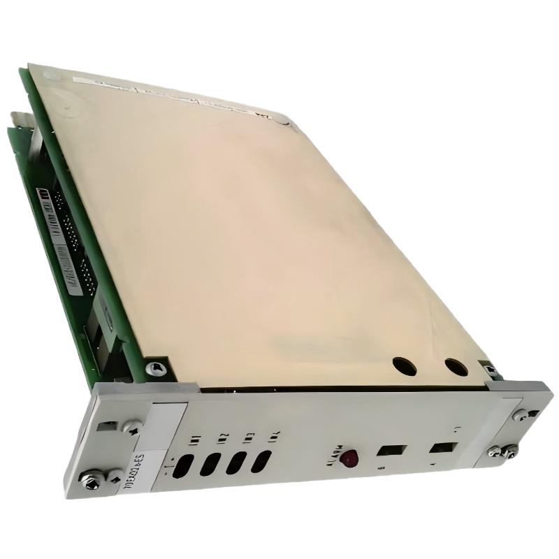
ABB 70EA02A-ES HESG447308R1 Input Module Fault Symptoms
ABB 70EA02A-ES HESG447308R1 Troubleshooting should begin with the signal path, not with immediate module replacement. A missing or incorrect process value can originate from the transmitter, loop wiring, terminal connection, channel configuration, power path, or input module itself. The 70EA02A-ES is documented as an input module for four two-wire transmitter channels in the ABB Procontrol P13 environment.
- One channel remains at zero or near zero.
- A process value is fixed despite a changing field condition.
- Several channels become abnormal at the same time.
- The displayed value does not correspond to the measured loop current.
- Intermittent signal fluctuations appear during plant operation.
- The channel reports an abnormal or invalid input condition.
ABB 70EA02A-ES Fault Diagnosis Thinking Process
The fastest troubleshooting method is to divide the system into four sections: field instrument, transmission loop, input channel, and DCS configuration. This prevents an engineer from replacing an expensive legacy module when the actual fault is a broken field conductor or incorrect scaling.
- Determine whether the fault affects one channel or several channels.
- Measure the field loop current.
- Compare the measured current with the DCS value.
- Check channel wiring and termination.
- Review System Configuration and channel assignment.
- Only after these checks should module-level hardware testing become the primary focus.
ABB 70EA02A-ES Input Channel Fault Case Analysis
Consider a commissioning fault in which an operator reports that a pressure indication remains close to zero while the transmitter is operating. The first useful measurement is not a board swap. Measure the loop current at the cabinet.
If the transmitter loop is approximately 16 mA but the DCS input remains near zero, the investigation moves downstream toward the termination, channel path, configuration, or input hardware. If the measured loop itself is near 0 mA, attention should instead move toward the transmitter, loop supply, cable, or field termination.
This diagnostic separation is especially useful with legacy DCS installations because several visually similar faults can produce the same operator-screen symptom.
ABB 70EA02A-ES Signal Comparison for Troubleshooting
Use three checkpoints whenever possible:
- Field value: transmitter process measurement.
- Loop value: actual current measured in the field circuit.
- DCS value: value received and displayed by the control system.
For example, if a controlled 12.00 mA test signal reaches the cabinet but the corresponding DCS value does not change, the engineer has already eliminated a large part of the field instrument problem. This is a much stronger Fault Diagnosis method than replacing components based only on the operator display.
IF loop_current == 0 mA:
    inspect transmitter / supply / wiring

IF loop_current is correct AND DCS_value is wrong:
    inspect channel / termination / configuration

IF several channels fail together:
    inspect rack power / common wiring / module path

IF one channel fails intermittently:
    inspect terminals / connector / channel circuit
Common Causes of ABB 70EA02A-ES Input Module Faults
- Open transmitter loop.
- Incorrect polarity or termination.
- Loose cabinet terminal connection.
- Incorrect channel assignment in System Configuration.
- Improper analog scaling.
- Electrical interference entering the signal wiring.
- Common power or rack-side problems affecting multiple channels.
- Actual input-channel hardware failure.
ABB 70EA02A-ES Troubleshooting and Repair Strategy
Repair decisions should follow measured evidence. When only one channel is abnormal and the field loop is confirmed healthy, compare the affected channel against a known-good channel under equivalent conditions. This comparison can reveal whether the problem follows the field wiring or remains associated with the module channel.
For an obsolete or legacy Procontrol installation, preserve the failed module until the root cause has been established. The 70EA02A-ES is identified by suppliers as a discontinued/legacy component, so unnecessary replacement of a serviceable board can consume limited spare inventory.
ABB 70EA02A-ES Fault Recovery and Commissioning Validation
After correcting the suspected fault, do not close the maintenance task simply because the operator display has returned to normal. Validate the complete signal path under at least one known operating condition.
- Confirm the measured loop signal.
- Verify the DCS channel value.
- Check engineering-unit scaling.
- Observe the signal for stability.
- Confirm that alarms clear correctly.
- Compare the repaired channel with adjacent healthy channels.
- Document the root cause and corrective action.
ABB 70EA02A-ES Field Troubleshooting Patterns
A useful field rule is to look for the fault distribution before opening the cabinet. One abnormal channel usually points toward the individual loop, terminal, configuration, or channel circuit. Several channels changing simultaneously suggests a common dependency such as rack power, common wiring, or system-side configuration.
Likewise, a stable but incorrect value is different from a rapidly fluctuating value. A stable error often justifies checking scaling or configuration early, while intermittent fluctuations should lead the investigation toward terminals, shielding, grounding, signal integrity, and mechanical connection quality.
ABB 70EA02A-ES Troubleshooting FAQ
What should be checked first when one ABB 70EA02A-ES channel shows zero?
Measure the associated transmitter loop current first. This separates a field-loop problem from a DCS input problem before module replacement is considered.
What does a correct loop current with an incorrect DCS value indicate?
It indicates that the field transmitter is producing a usable signal, so investigation should continue through the terminal connection, input channel, configuration, scaling, and module signal path.
Why can several ABB 70EA02A-ES channels fail at the same time?
Multiple simultaneous channel abnormalities can indicate a common power, rack, termination, configuration, or system-side problem rather than independent transmitter failures.
How can a known-good channel help with Fault Diagnosis?
Comparing the affected channel with a healthy channel under similar signal conditions provides a practical reference for identifying differences in wiring, signal level, configuration, or channel behavior.
Should the ABB 70EA02A-ES be replaced immediately after an input fault?
No. Field current, wiring, termination, channel configuration, and common system dependencies should be checked first. Replacement is more defensible after the external signal path has been verified.
What can cause an intermittent input value?
Possible causes include loose terminals, unstable transmitter output, cable or shielding problems, electrical interference, grounding issues, and intermittent channel hardware behavior.
How should a repaired input channel be validated?
Verify the physical loop signal, DCS value, engineering scaling, alarm behavior, and signal stability. A controlled test signal can be used where the plant procedure permits it.
Is the ABB 70EA02A-ES suitable for legacy Procontrol maintenance?
The module is associated with the ABB Procontrol P13 system and is identified by current aftermarket references as a legacy or discontinued component. Maintenance teams should therefore verify exact hardware identification before selecting a replacement.
ABB 70EA02A-ES Troubleshooting and Fault Diagnosis Summary
Effective ABB 70EA02A-ES Troubleshooting depends on separating field, loop, input-channel, and configuration faults. Measuring the actual transmitter current before replacing hardware provides a clearer Fault Diagnosis path and reduces unnecessary module swaps. For legacy Procontrol systems, documenting the measured signal, root cause, corrective action, and final commissioning result is particularly valuable for future maintenance.
 ABB PM572 1SAP130200R0200 CPU Module Troubleshooting Guide
 ABB 89AS30 GKWN000317R0100 Analog Signal Multiplier Troubleshooting Guide
 ABB PM510 3BSE000270R1 CPU Board Troubleshooting Guide
 ABB 89AR30/R0100 Relay Unit Troubleshooting Guide For Control And Protection Faults