100% Original, Ready to Ship!

ABB 83SR51 GJR2396200R1210 Control Module Troubleshooting Guide
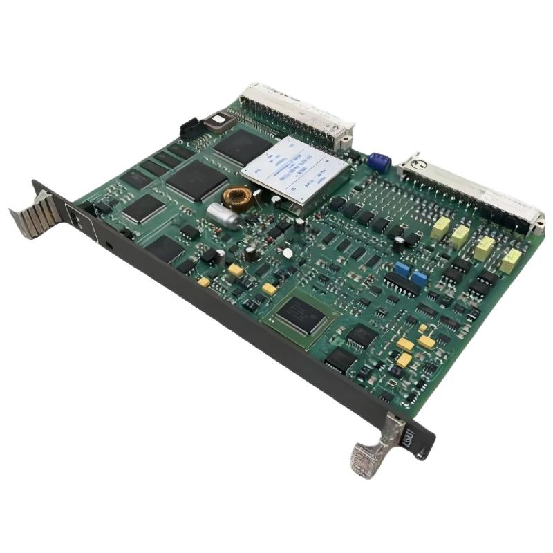
ABB 83SR51 GJR2396200R1210 Control Module Fault Diagnosis
ABB 83SR51 GJR2396200R1210 faults should be investigated by separating configuration, memory, I/O signal, and hardware problems before replacing the Control Module. One documented P14-related failure pattern involves application programs being written to RAM but not being completely transferred to Flash, which can result in an application read-back problem and a “Disable, list code not found” message. :contentReference[oaicite:4]{index=4}
ABB 83SR51 Control Module Fault Symptoms
Fault behavior can appear in several different forms. A module may operate normally at first but fail after a power cycle, an analog value may become implausible, an output may not follow the configured command, or the engineering software may report an application or memory-related condition.
- Unexpected module diagnostic indication.
- Incorrect or frozen analog process value.
- Digital input state does not correspond to the field condition.
- Output command does not produce the expected field response.
- Application data cannot be read back correctly.
- Application appears to disappear after module removal or power interruption.
- PDDS reports an application-related error.
ABB 83SR51 Troubleshooting Through a Fault Thinking Process
Do not start Fault Diagnosis by assuming that the PCB has failed. The first question should be whether the problem follows the signal, the configuration, the application memory, or the physical module.
A useful investigation sequence is:
- Determine whether the fault affects one channel or the entire module.
- Compare the control-system indication with a physical measurement.
- Check whether the fault survives a configuration reload.
- Check application storage and read-back behavior.
- Inspect module identification and production information where applicable.
- Only then evaluate suspected hardware failure.
ABB 83SR51 I/O Signal Troubleshooting
When only one analog channel is abnormal, compare that channel with another known-good channel under controlled conditions. If the field signal is correct but the displayed value is wrong, verify signal scaling and System Configuration before condemning the module.
For digital points, check the field contact or switching device independently. A permanently active input can originate from a field wiring fault, an incorrect common reference, or an incorrect configuration rather than from the Control Module itself.
For outputs, establish whether the control system is actually issuing the expected command. An output circuit should not be judged solely from the actuator’s final movement because interlocks, permissives, and downstream equipment can prevent the physical response.
ABB 83SR51 Application Memory Fault Diagnosis
A particularly important Troubleshooting path concerns application-program storage. A documented P14 service description explains a condition in which the application is initially written to RAM and should subsequently be copied into Flash. If the Flash transfer is incomplete, PDDS may report that the operation completed after the RAM write even though the application cannot later be read correctly from Flash. :contentReference[oaicite:5]{index=5}
This creates a critical diagnostic clue: if the application appears acceptable immediately after loading but disappears after removing and reinstalling the module, volatile RAM retention alone cannot be treated as proof that permanent application storage is healthy.
READ APPLICATION
CHECK READ-BACK RESULT
CHECK MODULE IDENTIFICATION
CHECK APPLICATION STORAGE
COMPARE AFTER POWER CYCLE
CHECK PDDS DIAGNOSTIC MESSAGE
ABB 83SR51 Documented Fault Case
A documented service case for 83SR51-related modules describes problems with writing and reading application programs through PDDS. The reported behavior involved application data being written to RAM while copying to Flash was incomplete or absent. Reading the application back from Flash could then produce the message “Disable, list code not found.” The same documentation notes that removing and reinstalling the module clears the volatile RAM copy, making the problem visible after a restart. :contentReference[oaicite:6]{index=6}
The engineering lesson is important: a successful initial download does not necessarily prove that the permanent application-storage process has completed correctly. If the same application disappears after module removal, memory persistence becomes a primary diagnostic direction.
ABB 83SR51 Hardware Identification During Troubleshooting
When a memory-related fault is suspected, record the module identification, hardware index, production information, and serial number before replacing the unit. The documented service information specifically describes checking the production date from the module or connector label and using GAF/OVE functionality of PDDS where applicable. :contentReference[oaicite:7]{index=7}
This information can be useful because replacing a module without recording its identity can remove valuable evidence about the failure pattern.
ABB 83SR51 Repair and Recovery Strategy
Repair should be divided into recovery of the control application and determination of the underlying hardware condition. If the application is recoverable, preserve the validated configuration before performing further tests. If the application cannot be retained correctly, investigate the documented RAM-to-Flash behavior and applicable module revision or production information.
- Preserve the existing application and configuration where possible.
- Record diagnostic messages exactly as displayed.
- Record module identification and hardware information.
- Check application write and read-back behavior.
- Perform controlled power-cycle verification.
- Compare the suspected module with an approved known-good unit only after configuration evidence has been preserved.
ABB 83SR51 Signal Analysis During Fault Diagnosis
For I/O-related faults, measured data is more useful than a general statement such as “the input is unstable.” For example, record the field signal, the value displayed by the control system, and the time of observation. A commissioning test might record a 12.00 mA simulated input and the corresponding configured process value. If the physical signal remains stable while the software value jumps between states, the diagnostic focus should move away from the transmitter itself.
Likewise, if a digital input is measured as electrically stable but the software state changes intermittently, investigate the input circuit, reference connection, configuration, and module behavior systematically.
ABB 83SR51 Repair Validation and Return to Service
After corrective work, do not return the module to service solely because the alarm has disappeared. Repeat the original failure test. For a memory-related issue, verify application read-back and then perform an appropriate restart or power-cycle validation. For an I/O fault, reproduce the field signal and confirm that the control-system value and final output response remain correct.
ABB 83SR51 Troubleshooting Guide FAQ
What is a common ABB 83SR51 fault pattern?
One documented P14-related fault pattern concerns application data being written to RAM without being completely copied to Flash. A later read-back operation can then fail with an application-related message. :contentReference[oaicite:8]{index=8}
Why can an ABB 83SR51 appear normal immediately after downloading an application?
The application may initially exist in volatile RAM even if permanent storage has not completed correctly. A subsequent restart or module removal can therefore expose the underlying storage problem.
What does “Disable, list code not found” indicate in the documented case?
In the documented failure pattern, the message was associated with an inability to retrieve valid application data from Flash after the RAM-to-Flash transfer had not completed correctly. :contentReference[oaicite:9]{index=9}
Should an ABB 83SR51 be replaced immediately when an analog value is incorrect?
No. Verify the field signal, wiring, channel assignment, scaling, configuration, and control logic first. Hardware replacement should follow evidence that isolates the module as the fault source.
How can a technician investigate an intermittent 83SR51 input?
Record the physical signal and software value simultaneously, then compare the behavior with a controlled test signal. This helps separate field-device instability from wiring, configuration, or module-level problems.
What information should be recorded before replacing an 83SR51?
Record the complete product identification, hardware information, production or date code where available, serial number, active diagnostics, application status, and relevant field measurements. Documented service guidance also recommends identifying production information when investigating affected modules. :contentReference[oaicite:10]{index=10}
ABB 83SR51 Troubleshooting Guide Conclusion
Effective ABB 83SR51 GJR2396200R1210 Troubleshooting depends on separating an I/O problem from a configuration problem and a genuine module fault. The documented application-memory failure pattern demonstrates why read-back verification and restart testing are important parts of Fault Diagnosis. A controlled measurement, documented configuration, and repeatable recovery test provide a stronger basis for repair than simply replacing the Control Module.
 ABB PM572 1SAP130200R0200 CPU Module Troubleshooting Guide
 ABB 89AS30 GKWN000317R0100 Analog Signal Multiplier Troubleshooting Guide
 ABB PM510 3BSE000270R1 CPU Board Troubleshooting Guide
 ABB 89AR30/R0100 Relay Unit Troubleshooting Guide For Control And Protection Faults