100% Original, Ready to Ship!

ABB 87TS01I-E GJR2368900R2200 Coupler Module Troubleshooting and Fault Diagnosis
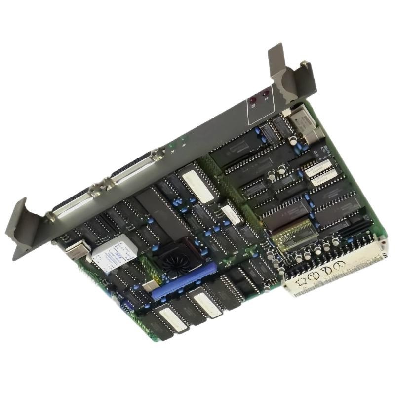
ABB 87TS01I-E Coupler Module Troubleshooting Overview
ABB 87TS01I-E GJR2368900R2200 Coupler Module communication problems should be investigated by separating power-related symptoms, hardware recognition issues, and communication failures within the control system. In a PROCONTROL P14 installation, the coupler is associated with system communication and station-level data handling, so a communication alarm does not automatically prove that the module itself has failed.
Effective Troubleshooting begins with the fault history, module status, controller diagnostics, and the behavior of connected stations. Before attempting a repair, confirm the installed part number and its intended function using the equipment documentation.
ABB 87TS01I-E Coupler Module Fault Symptoms and Evidence
Several symptoms can point toward a coupler-related problem, but each requires a different diagnostic path.
- Module not recognized: The engineering or diagnostic system does not identify the expected hardware.
- Intermittent communication: Data exchange becomes unstable or communication alarms appear periodically.
- Station unavailable: One or more connected stations cannot be reached through the expected communication path.
- Unexpected diagnostic messages: The system reports a configuration mismatch or communication-related event.
- Repeated recovery attempts: Communication returns temporarily but fails again under similar operating conditions.
Note the time of each event and whether several devices fail simultaneously. Multiple stations becoming unavailable at the same moment may indicate a shared communication-path or system-level issue rather than several independent hardware failures.
ABB 87TS01I-E Fault Diagnosis Through a Structured Investigation
Start by preserving diagnostic information before resetting alarms or changing configuration parameters. A reset can remove useful evidence and make an intermittent fault more difficult to reproduce.
- Establish the fault boundary. Determine whether the issue affects one station, a complete communication segment, or the entire controller system.
- Review the event sequence. Compare the first alarm with preceding power interruptions, maintenance work, configuration changes, or cable disturbances.
- Inspect hardware connections. Under the approved isolation procedure, check the module seating, connector condition, and any associated communication cabling.
- Compare the System Configuration. Verify the configured hardware identity and communication arrangement against the actual installation.
- Test one suspected cause at a time. Record each change and check whether the original symptom disappears.
ABB 87TS01I-E Coupler Module Diagnostic Command Examples
The following is a platform-neutral diagnostic checklist written as pseudocode. It is not executable ABB software syntax; use the approved engineering tools and diagnostic commands for the installed system.
BEGIN_FAULT_DIAGNOSIS
  READ module_identity
  READ module_status
  READ communication_events
  CHECK configured_hardware_against_installed_hardware
  CHECK affected_station_availability
  SAVE diagnostic_snapshot
  IF fault_persists:
      ISOLATE the affected communication path
      VERIFY connections and approved parameters
      RETEST under controlled conditions
  END_IF
END_FAULT_DIAGNOSIS
Do not enter arbitrary commands into a live PLC Controller or DCS. The diagnostic method must match the actual controller generation, software environment, and service documentation.
ABB 87TS01I-E Communication Fault Root Cause Analysis
When communication is intermittent, investigate the timing and distribution of the failures before replacing hardware. If multiple stations lose communication together, inspect shared infrastructure and common configuration dependencies. If only one connection is affected, focus on that path, its connectors, and the associated device configuration.
For suspected electrical problems, qualified personnel should compare measurements with the documented supply and interface limits. Do not apply generic voltage, resistance, or termination values without confirming the correct interface specification for this exact variant.
In one representative diagnostic scenario, communication alarms recur after maintenance even though the system starts normally. A practical investigation would compare the pre-maintenance and current configurations, inspect disturbed connections, and correlate the alarm timestamps with other station events. If restoring a verified configuration or correcting a documented connection resolves the issue, the evidence supports a configuration or connection-related cause. This scenario illustrates an engineering method; it is not a verified repair record for this specific module.
ABB 87TS01I-E Coupler Module Repair and Recovery Strategy
Choose corrective action only after the fault has been narrowed to a credible cause. Randomly reseating modules, changing multiple parameters, or repeatedly restarting the controller can introduce new problems and destroy diagnostic evidence.
- Configuration mismatch: Restore or correct the approved configuration after validating the intended hardware arrangement.
- Loose or damaged connection: Isolate the equipment as required and repair or replace the affected connection using approved components.
- Communication-path problem: Inspect the relevant segment, connectors, cable routing, and documented interface settings.
- Suspected module failure: Confirm the diagnosis using supported tests and, where possible, a verified compatible replacement.
- Unresolved or recurring fault: Escalate with the diagnostic snapshot, event timeline, hardware identity, and completed test results.
Any module substitution must use a confirmed compatible part and an authorized change procedure. Do not assume that visually similar couplers or neighboring order codes are interchangeable.
ABB 87TS01I-E Troubleshooting Verification After Repair
After corrective work, confirm more than the disappearance of the original alarm. Check that the module is recognized, expected stations are available, and normal data exchange resumes. Review the event log for recurring errors and observe the system for an appropriate period under controlled operating conditions.
Document the original symptom, confirmed root cause, action taken, post-repair status, and any remaining restrictions. Where numerical measurements are relevant, record actual readings together with their measurement points, units, test conditions, and applicable specification limits.
ABB 87TS01I-E Coupler Module Troubleshooting FAQ
What is the first check when the ABB 87TS01I-E stops communicating?
Preserve the diagnostic log, identify which stations are affected, and check the module status and recent system events before resetting the equipment.
Does a communication alarm confirm that the coupler is defective?
No. Configuration errors, connection problems, communication-path faults, and problems in other system components can produce similar symptoms.
Why does communication return after a restart but fail again?
A restart may temporarily clear a symptom without correcting its underlying cause. Investigate recurring event patterns, configuration consistency, and connection stability.
Can a different 87TS01 series module be used for replacement?
Compatibility must be established from ABB documentation and the installed system requirements. Similar model names alone are insufficient evidence of interchangeability.
What evidence is useful when requesting technical repair support?
Provide the complete order number, system identification, fault timestamps, diagnostic messages, configuration details, inspection findings, and results of controlled tests.
ABB 87TS01I-E Coupler Module Fault Diagnosis Conclusion
Reliable ABB 87TS01I-E GJR2368900R2200 Coupler Module Troubleshooting depends on identifying the fault boundary, preserving evidence, verifying the System Configuration, and testing the communication path systematically. Replace the Module only when diagnostic results support hardware failure. The final repair and commissioning checks should follow the applicable ABB documentation and the site’s approved maintenance procedures.
 ABB PM572 1SAP130200R0200 CPU Module Troubleshooting Guide
 ABB 89AS30 GKWN000317R0100 Analog Signal Multiplier Troubleshooting Guide
 ABB PM510 3BSE000270R1 CPU Board Troubleshooting Guide
 ABB 89AR30/R0100 Relay Unit Troubleshooting Guide For Control And Protection Faults