100% Original, Ready to Ship!

ABB 87TS01I-E GJR2368900R2313 Coupler Module Troubleshooting Guide
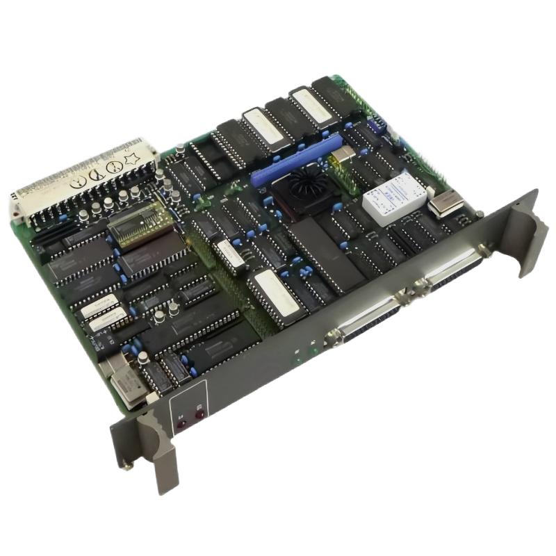 ABB 87TS01I-E Coupler Module Fault Diagnosis Contents
- Initial Fault Observations
- Communication Fault Diagnosis Logic
- Power and Interface Checks
- Coupler Module Recovery and Verification
- Field Investigation Example
- Troubleshooting FAQ
- Final Fault Assessment
ABB 87TS01I-E Coupler Module Fault Symptoms
When a coupler stops exchanging data with the associated control system, the visible symptoms may include an unexpected interface status, missing data, communication alarms, or loss of access to connected equipment. These symptoms do not independently prove that the coupler itself is defective.
Start by documenting what changed immediately before the fault appeared. A recent module replacement, cabinet maintenance activity, power interruption, wiring modification, or system configuration update can provide more useful diagnostic evidence than the alarm description alone.
- Module not recognized: Inspect the approved mounting position, connector engagement, module identification, and compatibility.
- Intermittent communication: Investigate loose connections, unstable supply conditions, cable damage, and interface disturbances.
- Persistent communication alarm: Review system diagnostics, addressing, configuration records, and the status of connected equipment.
- Fault following replacement: Compare the replacement part number and hardware revision with the approved configuration.
ABB 87TS01I-E Communication Fault Diagnosis Logic
A useful Fault Diagnosis approach begins with the scope of the failure. If several connected devices become unavailable at the same time, investigate common components such as the power source, shared interface, rack connection, or communication path. If only one connection is affected, prioritize its individual wiring, configuration, and endpoint.
Use the following diagnostic sequence to organize the investigation:
- Establish whether the fault is continuous, intermittent, or associated with startup.
- Check whether other modules or communication paths show the same symptom.
- Review the alarm history and identify the earliest relevant event.
- Verify supply measurements against the specifications for the confirmed hardware.
- Inspect physical connections and compare the installed configuration with approved records.
- Use supported diagnostic tools to determine whether the failure originates locally or elsewhere in the system.
Diagnostic workflow (pseudocode)

capture_alarm_history()
classify_fault_scope()
compare_affected_and_healthy_nodes()
verify_supply_against_specification()
inspect_connectors_and_cabling()
review_approved_system_configuration()
isolate_confirmed_fault_source()
document_test_results()
This pseudocode describes an engineering workflow, not native ABB commands. Execute actual diagnostic operations through the tools and procedures approved for the installed control platform.
ABB 87TS01I-E Coupler Module Electrical Troubleshooting
Electrical measurements should be taken at documented test points with instruments suitable for the circuit. Compare readings with the manufacturer’s limits and, where practical, with a known-good operating condition. A measurement taken at a power supply does not necessarily represent the voltage reaching the module under load.
- Supply integrity: Check the specified supply at the appropriate terminals and inspect for abnormal fluctuation during startup or load changes.
- Connector condition: Look for damaged contacts, contamination, incomplete engagement, or signs of overheating.
- Communication path: Verify cable continuity, shielding, grounding, connector pin assignments, and termination where applicable to the confirmed interface.
- Configuration consistency: Compare the configured module identity and interface settings with the approved system documentation.
- Diagnostic evidence: Correlate status indicators and system alarms with the timing of the observed failure.
Do not apply assumed voltage limits, pin assignments, or resistance thresholds to an unidentified revision. If a test requires live measurements, follow the site’s electrical safety procedure and use appropriately rated equipment.
ABB 87TS01I-E Coupler Module Troubleshooting and Recovery
Recovery should follow identification of a credible root cause. Correcting a loose connector, restoring a documented configuration, or repairing an external cable may resolve a communication problem without replacing the coupler. Conversely, persistent faults after verified external checks may justify further module-level testing or controlled substitution.
- Correct any confirmed wiring or connector problem using the approved maintenance procedure.
- Restore configuration settings from a verified backup when configuration corruption has been established.
- Replace the module only after confirming compatibility and following the specified shutdown or replacement procedure.
- Repeat the original test conditions and verify that the alarm clears and communication remains stable.
- Record the corrective action, measurements, configuration changes, and post-repair results.
A successful restart alone is not proof of permanent recovery. For intermittent faults, observe the system under representative operating conditions and check whether the original symptom returns.
ABB 87TS01I-E Coupler Module Field Investigation Example
Consider a representative industrial maintenance case in which communication alarms appear after a control cabinet has been serviced. The first observation is that multiple devices on the same interface report interruptions, while other control functions continue operating normally.
The engineer initially considers module failure, supply instability, and a disturbed shared connection. Alarm timestamps are compared with the maintenance log, followed by inspection of the shared interface and verification of the supply against the applicable specification. If the supply is stable and the alarms coincide with a loose or incompletely seated connection, that connection becomes the leading cause to test.
After the connection is corrected under the approved isolation procedure, the engineer repeats the communication test and monitors the alarm history. The diagnosis is accepted only if the evidence supports the cause and the original symptom no longer occurs under the relevant operating conditions. This is an illustrative fault-investigation scenario, not a claim of a documented repair on a specific ABB installation.
ABB 87TS01I-E Coupler Module Troubleshooting FAQ
Why does the ABB 87TS01I-E Coupler Module show a communication fault?
Possible causes include power instability, connector problems, damaged cabling, incompatible hardware, incorrect interface settings, or a fault elsewhere in the connected system. Use diagnostic evidence to distinguish these possibilities.
How can engineers distinguish a coupler failure from a network problem?
Compare the affected communication path with healthy paths, inspect shared connections, review diagnostic records, and verify electrical conditions before performing an approved substitution test.
Should the coupler be reset immediately after an alarm?
Capture the alarm history and relevant operating conditions first. Resetting may clear useful evidence, and a reset will not correct an underlying wiring, compatibility, or hardware problem.
When is replacement of the coupler justified?
Replacement becomes reasonable when external connections, supply conditions, compatibility, and system configuration have been checked and the remaining evidence points to a module fault. Confirm the replacement part and revision before installation.
What should be checked if the fault returns after repair?
Compare the new alarm timestamps with the original event, inspect intermittent connections, review supply behavior under load, and determine whether the fault follows a particular interface, operating condition, or component.
ABB 87TS01I-E Coupler Module Troubleshooting Conclusion
Reliable troubleshooting of the ABB 87TS01I-E Coupler Module depends on identifying the exact hardware, establishing the scope of the communication fault, checking electrical and interface conditions, and validating the corrective action. Avoid replacing components based solely on an alarm or an unsuccessful restart. For GJR2368900R2313, confirm the relationship between the stated model designation and ordering code before using model-specific wiring diagrams, voltage limits, or repair instructions. This final verification helps prevent an incorrect replacement and supports a traceable maintenance decision.
 ABB PM572 1SAP130200R0200 CPU Module Troubleshooting Guide
 ABB 89AS30 GKWN000317R0100 Analog Signal Multiplier Troubleshooting Guide
 ABB PM510 3BSE000270R1 CPU Board Troubleshooting Guide
 ABB 89AR30/R0100 Relay Unit Troubleshooting Guide For Control And Protection Faults