100% Original, Ready to Ship!

ABB 87TS01I-E GJR2368900R2342 Coupler Module Troubleshooting And Fault Diagnosis Guide
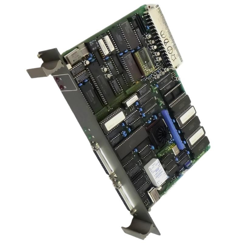
ABB 87TS01I-E Coupler Module Troubleshooting: Start with Communication Evidence
ABB 87TS01I-E GJR2368900R2342 Coupler Module communication problems should be investigated by separating hardware recognition, configuration compatibility, physical connection quality, and endpoint communication. A missing connection or intermittent data exchange does not automatically indicate coupler failure. Effective Fault Diagnosis begins by identifying which communication function has stopped working and determining whether the fault follows the module, the cable, the configuration, or the connected equipment.
Before changing parameters or replacing hardware, capture the current alarm messages, module identification, system status, and available diagnostic counters. These observations establish a baseline for a controlled Troubleshooting process.
ABB 87TS01I-E Fault Symptoms and Their Diagnostic Meaning
Different symptoms point toward different fault categories. The following table is a starting point for investigation, not a substitute for the platform-specific diagnostic manual.
| Observed symptom | Possible causes | Initial diagnostic check |
|---|---|---|
| Module not recognized | Incorrect slot assignment, poor seating, incompatible hardware, or rack-interface problem | Verify module identity, mounting position, and system hardware diagnostics |
| Communication unavailable | Incorrect configuration, disconnected cable, incompatible interface settings, or endpoint failure | Compare both endpoints’ parameters and inspect the physical connection |
| Intermittent communication | Loose connector, electrical interference, cable damage, or unstable configuration | Review event history, communication counters, and cable condition |
| Fault returns after restart | Persistent configuration mismatch, recurring electrical issue, or hardware fault | Compare the fault sequence before and after restart |
| Communication works with one endpoint but not another | Endpoint-specific settings, wiring differences, or compatibility issues | Compare the working and failed connections without changing multiple variables |
ABB 87TS01I-E Coupler Module Fault Diagnosis by Isolation
A useful diagnostic sequence narrows the fault domain before any component is replaced. Begin with the least intrusive checks and move toward hardware isolation only when the evidence supports it.
- Hardware recognition: Determine whether the host system detects the module and reports the expected identity.
- Configuration: Check for unsupported hardware revisions, incorrect assignments, or parameter mismatches.
- Physical connection: Inspect connectors, cable routing, shielding, and any specified termination.
- Endpoint status: Establish whether the connected device is powered, operational, and configured for the same interface settings.
- Hardware condition: Consider a defective coupler only after the preceding checks and approved substitution tests provide supporting evidence.
Do not change several settings simultaneously. If communication returns after multiple modifications, the root cause remains uncertain and the repair may be difficult to reproduce.
ABB 87TS01I-E Communication Faults: Cable and Interface Checks
Physical communication faults can resemble internal module failures. A connector may appear secure while a conductor is broken, a contact is damaged, or shielding is terminated incorrectly. Interference from nearby switching equipment can also produce intermittent errors that are absent during a short stationary test.
During a safe inspection, check the following:
- Verify that the cable and connector types match the approved interface specification.
- Inspect for loose connector shells, bent contacts, corrosion, and mechanical strain.
- With equipment isolated as required, test cable continuity and check for unintended shorts.
- Compare the interface mode, communication rate, addressing, and other applicable parameters at both endpoints.
- Review whether the fault correlates with motor starts, contactor switching, or other electrical disturbances.
Use only the interface limits specified for the actual hardware and communication standard. Do not apply an arbitrary test voltage to a communication pin or perform live probing without an approved procedure.
ABB 87TS01I-E System Configuration Errors and Recovery
If the module is recognized but communication does not start, review the configuration before concluding that the hardware has failed. A replacement can have the correct family designation yet still be unsuitable for the specific installation because of differences in ordering code, revision, or supported system configuration.
Compare the current configuration with the last known-good backup. Check module assignment, endpoint parameters, firmware compatibility, and any system-specific communication settings documented by the manufacturer. Restore a known-good configuration only through the approved engineering process and after confirming that it matches the installed hardware.
For a diagnostic log or engineering worksheet, the following pseudo commands illustrate the sequence of checks. They are not executable ABB commands:
READ MODULE IDENTIFICATION
COMPARE CONFIGURATION REVISION
CHECK ENDPOINT PARAMETERS
REVIEW COMMUNICATION ERROR COUNTERS
SAVE DIAGNOSTIC RECORD
Use the actual diagnostic tools provided for the installed control platform. Preserve the original event log before clearing alarms or resetting counters.
ABB 87TS01I-E Troubleshooting Case: Fault Appears Only During Operation
In a representative industrial fault investigation, a communication link may work during a stationary test but become unreliable after production equipment starts. This pattern suggests that the engineer should examine operating conditions instead of immediately replacing the coupler.
The investigation should correlate timestamps from communication alarms with equipment starts, electrical switching, and changes in the connected device’s status. The next checks include connector retention, cable routing, shield termination, and endpoint parameters. If the fault occurs only when a particular device operates, inspect that device’s wiring and electrical environment while maintaining the site’s safety procedures.
For example, an increase in recorded communication errors from 0 to 18 during a defined observation period would be useful evidence if those values were obtained from the actual diagnostic counter. The figures here are illustrative, not measured results for the ABB 87TS01I-E. A valid repair report must state the real observation interval, recorded values, corrective action, and post-repair verification results.
ABB 87TS01I-E Coupler Module Repair and Replacement Decisions
Replacement should be the result of diagnosis rather than the first troubleshooting action. Consider a hardware exchange only after the module identity and configuration have been checked, the external communication path has been inspected, and the fault persists under an approved test procedure.
- Preserve the fault log and current configuration before disturbing the installation.
- Follow the site’s isolation and electrostatic-discharge precautions before removing hardware.
- Verify the replacement ordering code and revision against the approved compatibility requirements.
- Inspect the rack interface and connectors before installing the replacement.
- After replacement, repeat the same communication test used to establish the original fault.
- Monitor the system for recurrence under representative operating conditions.
If the fault remains after a verified replacement, return to the system-level investigation. The rack, backplane, external cable, connected endpoint, or configuration may still be responsible.
ABB 87TS01I-E Coupler Module Troubleshooting FAQ
Why is the ABB 87TS01I-E not communicating with the host system?
Possible causes include incorrect hardware assignment, incompatible configuration, poor connector seating, cable faults, or a problem at the connected endpoint. Check hardware recognition and diagnostic messages before replacing the module.
Can a communication fault be caused by incorrect System Configuration?
Yes. Incorrect hardware assignments, interface parameters, or incompatible configuration revisions can prevent communication even when the physical installation appears correct. Compare the current configuration with an approved backup.
How can intermittent coupler faults be investigated?
Record communication counters and alarm timestamps, inspect cable and connector condition, and correlate failures with operating events. A longer observation period may reveal patterns that a brief commissioning test misses.
When should the Coupler Module be replaced?
Replacement is appropriate when the fault persists after documented configuration and wiring checks and an approved diagnostic or substitution procedure supports a hardware-related cause. Confirm the replacement’s exact compatibility first.
Should diagnostic counters be cleared during Troubleshooting?
Capture the original values and event history before clearing any counter. Follow the platform’s documented procedure, then record the observation interval and counter values after corrective action so the result can be evaluated.
ABB 87TS01I-E Fault Diagnosis: Final Engineering Summary
Reliable ABB 87TS01I-E GJR2368900R2342 Coupler Module Troubleshooting depends on evidence-based fault isolation. Separate hardware recognition, System Configuration, physical communication, and endpoint behavior before deciding whether repair or replacement is necessary. Preserve diagnostic records, change one variable at a time, and verify the result under representative operating conditions. Because model-specific interface details and diagnostic commands must be confirmed against the applicable ABB documentation, avoid relying on unverified pin assignments, assumed electrical values, or undocumented reset procedures.
 ABB PM572 1SAP130200R0200 CPU Module Troubleshooting Guide
 ABB 89AS30 GKWN000317R0100 Analog Signal Multiplier Troubleshooting Guide
 ABB PM510 3BSE000270R1 CPU Board Troubleshooting Guide
 ABB 89AR30/R0100 Relay Unit Troubleshooting Guide For Control And Protection Faults