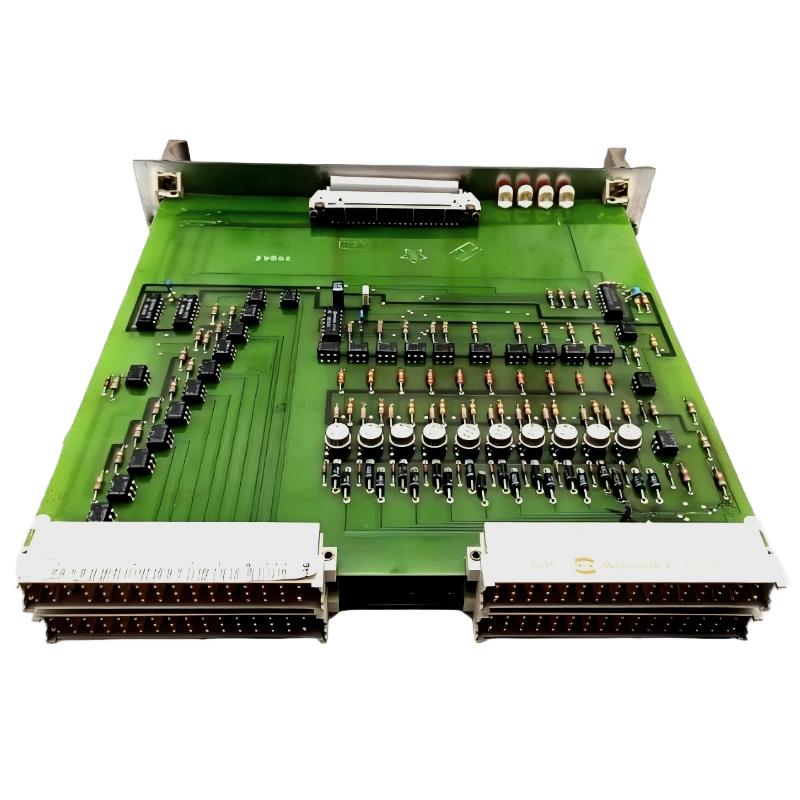
ABB PM510 3BSE000270R1 CPU Board Troubleshooting and Fault Diagnosis
ABB PM510 3BSE000270R1 CPU Board faults should be investigated by checking controller status, hardware compatibility, memory-related issues, communication behavior, and the installed Advant Controller configuration before replacing the processor module. In legacy industrial control systems, a controller that fails to start or communicate does not automatically indicate a defective CPU board. A structured Troubleshooting process helps distinguish a board failure from an external interface problem or an application-related fault.
ABB PM510 CPU Board Fault Diagnosis Contents
- Recognizing CPU Board Fault Patterns
- Engineering Investigation Strategy
- Diagnostic Checks and Evidence
- Corrective Actions and Recovery
- Field Troubleshooting Example
- Technical Troubleshooting FAQ
- Final Engineering Assessment
Recognizing ABB PM510 3BSE000270R1 CPU Board Fault Patterns
The first task in ABB PM510 Fault Diagnosis is to describe the failure precisely. Record whether the controller fails during startup, loses communication intermittently, stops executing its application, or develops recurring system alarms. These symptoms point toward different diagnostic paths.
- Controller startup failure: Investigate the power supply, processor hardware condition, memory or configuration dependencies, and startup diagnostics.
- Intermittent communication: Examine the communication interface, cable condition, connector integrity, network equipment, and diagnostic records.
- Unexpected controller stop: Review system events, application behavior, configuration changes, and any available processor diagnostics.
- Repeated faults after replacement: Check the replacement part number, hardware revision, system compatibility, and whether the original fault remains elsewhere in the control system.
- Unstable operation after maintenance: Investigate disturbed connections, installation errors, environmental conditions, and changes introduced during the work.
These are general diagnostic categories, not a claim that every symptom is a documented failure mode of this exact PM510 revision. Use the actual controller documentation to identify the relevant status indicators and supported diagnostic interfaces.
ABB PM510 CPU Board Troubleshooting: An Engineering Investigation Strategy
Before changing hardware, establish when the problem started and what changed immediately beforehand. An unexpected shutdown, a maintenance intervention, a configuration download, and a gradual increase in communication errors represent different fault histories.
A useful investigation begins with three questions:
- Is the fault local or system-wide? Determine whether other controller functions, associated modules, or supervisory interfaces are affected.
- Is the failure continuous or intermittent? Compare event timestamps and operating conditions to identify a repeatable pattern.
- Can the fault be reproduced without unsafe intervention? Use approved diagnostic procedures and avoid unnecessary resets that could erase useful evidence or interrupt a running process.
For example, if a supervisory workstation loses data while the controller continues executing its application, investigate the communication path before concluding that the CPU has stopped functioning. Conversely, if the controller itself cannot complete startup, network troubleshooting alone is unlikely to resolve the underlying problem.
ABB PM510 CPU Board Diagnostic Checks and Signal Analysis
Collect evidence in a fixed order so that each test narrows the possible causes. The precise measurement points and acceptable electrical values must come from the approved hardware documentation rather than assumed generic limits.
Controller Power and Hardware Condition
Confirm the supply conditions at the specified test points, inspect accessible connectors, and look for physical damage, contamination, corrosion, or overheating. Compare measured voltage with the documented operating range at the relevant interface. A nominal reading at the power supply does not necessarily prove that the correct voltage reaches the affected hardware under operating conditions.
Communication and Network Fault Diagnosis
When communication is unstable, record the affected interface, destination device, alarm timestamps, and any available error counters. Check cable seating, connector condition, shielding arrangements, and grounding against the system design. If other devices share the same network, determine whether they experience the same interruption.
Configuration and Application Review
Compare the current system configuration with the last known working record. Check whether approved maintenance has changed hardware, software, communication settings, or application data. Before attempting a download or firmware operation, verify that the procedure applies to the exact controller and that a valid recovery backup is available.
Diagnostic Record Template
Asset: ABB PM510 3BSE000270R1
Controller family: Verify from system documentation
Reported symptom: Record the actual fault
Fault start time: Record from event history
Power measurement: Actual value and test point
Status indicators: Record observed behavior
Communication errors: Record actual counters or messages
Configuration changes: Compare with approved baseline
Corrective action: Document each authorized change
Verification: Record results of approved functional tests
The entries above are a diagnostic record template, not commands for the ABB PM510. No model-specific voltage limit, LED sequence, or executable command should be assumed without the relevant manufacturer documentation.
ABB PM510 CPU Board Repair and System Recovery Procedures
Recovery should address the identified cause rather than simply clear the alarm. Use the corrective action that corresponds to the evidence collected during Fault Diagnosis.
- Connection fault confirmed: Correct the affected connection or cable in accordance with the electrical drawings and approved maintenance procedure.
- Hardware compatibility issue confirmed: Verify the complete ordering code and revision against the installed controller architecture before sourcing a replacement.
- Configuration problem identified: Restore or correct the configuration using an approved backup and the appropriate engineering procedure.
- Communication path problem confirmed: Repair the affected interface, cabling, or network component, then repeat the communication test.
- Suspected CPU board failure: Preserve the diagnostic evidence and arrange a controlled replacement or specialist bench assessment.
Do not perform firmware updates, memory changes, or configuration restoration as trial-and-error measures. An incorrect procedure can make an older control system more difficult to recover. Where the process is safety-critical, follow the plant’s approved shutdown, change-management, and restart requirements.
ABB PM510 CPU Board Troubleshooting: Illustrative Field Case
During a hypothetical maintenance investigation, an operator reports intermittent data loss between a legacy controller and the supervisory system. The initial assumption is that the ABB PM510 CPU Board is deteriorating because the problem appears to originate at the controller cabinet.
The engineer first checks the event history and finds that the controller’s reported application status remains consistent during the communication interruptions. The investigation then moves to the external communication path. Cable connections, interface status, and network records are compared against the approved system baseline. A connection problem is identified and corrected under the maintenance procedure.
After the correction, the engineer repeats the communication test, monitors the system for recurrence, and documents the results. The CPU board is not replaced because the available evidence does not establish an internal processor failure.
This is an illustrative engineering scenario, not a verified repair report for the specific ABB PM510 3BSE000270R1. For a real maintenance record, include the actual alarm messages, measured values, confirmed root cause, corrective work, and post-repair results. Do not publish invented measurement values as field evidence.
ABB PM510 3BSE000270R1 CPU Board Troubleshooting FAQ
What should be checked first when the ABB PM510 CPU Board fails to start?
Review the documented supply conditions, board identification and compatibility, connector seating, startup indications, and available controller diagnostics. Use the system-specific startup procedure to determine the next test.
Can communication loss confirm that the PM510 CPU Board is defective?
No. Communication loss can originate in the controller, communication interface, cabling, network equipment, or configuration. Compare controller operating status with network evidence before assigning the fault to the CPU board.
How can an engineer distinguish a CPU fault from a configuration problem?
Compare the fault history with configuration changes, verify the installed hardware against the approved design, and review the controller’s actual diagnostic messages. A configuration mismatch should be investigated before hardware replacement is authorized.
Should the ABB PM510 CPU Board be reset immediately after an alarm?
Not automatically. Capture the alarm message, timestamps, operating state, and relevant diagnostics first. Reset or restart the controller only when the approved recovery procedure permits it.
What evidence supports a CPU board replacement decision?
Useful evidence includes repeatable startup failures, documented internal hardware diagnostics, verified power and connections, confirmed part compatibility, and results from approved isolation or specialist testing procedures.
Is firmware updating a suitable first response to a PM510 fault?
No. Confirm the exact controller version, firmware compatibility, approved update method, and recovery plan before any firmware operation. Firmware procedures for other ABB controller families must not be assumed to apply to this processor module.
What should be recorded after ABB PM510 CPU board repair?
Record the original symptoms, diagnostic evidence, measurements, confirmed root cause, parts or settings changed, functional test results, and authorization to return the system to service.
When should a suspected PM510 hardware failure be escalated?
Escalate when internal hardware failure remains likely after documented external checks, when diagnostics are inconclusive, or when further testing could compromise process availability or safety. Provide the complete part number, system details, fault history, and collected diagnostic records.
Final Engineering Assessment for ABB PM510 CPU Board Faults
Effective ABB PM510 3BSE000270R1 CPU Board Troubleshooting depends on separating processor-related faults from communication, configuration, power, and connection problems. A disciplined Fault Diagnosis process preserves evidence, reduces unnecessary hardware replacement, and makes recovery decisions easier to justify. Confirm every model-specific electrical limit, diagnostic indicator, and repair procedure against the applicable ABB documentation. Before restarting production, complete the approved functional checks and document the final system condition.