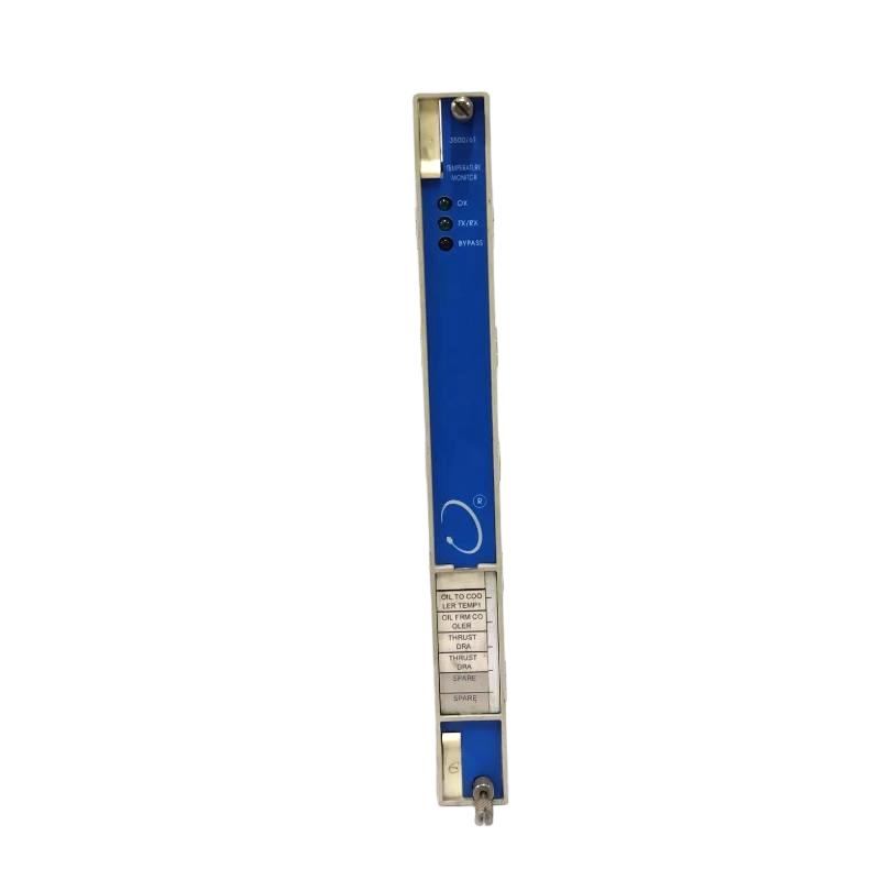
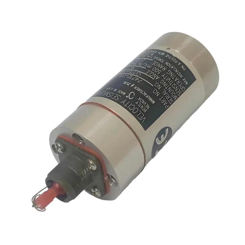
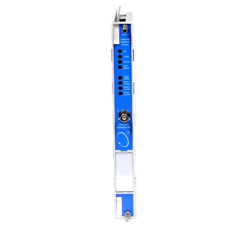
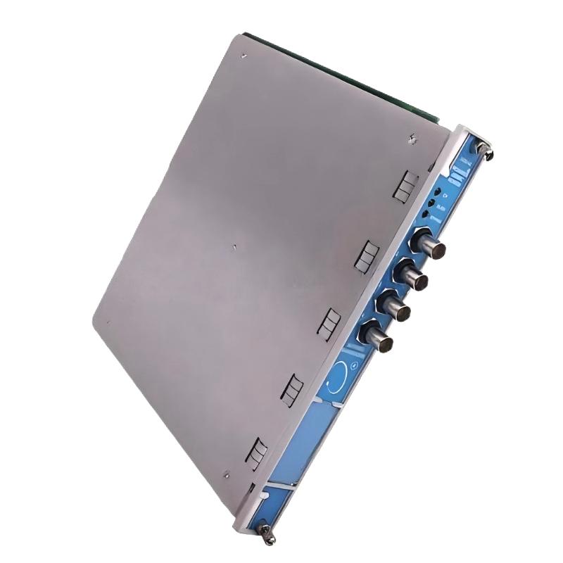
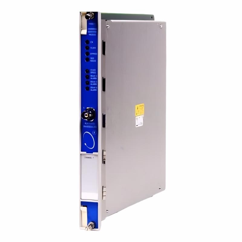
Bently Nevada 3500/53-03-00 Overspeed Detection Module
| Company Information | ||||||||
| [email protected] | ||||||||
| Mobile | +8613666084105 | |||||||
| +8613666084105 | ||||||||
| 13666084105 | ||||||||
| Add to | Room 1004, No. 62 Xiangxiu Li, Siming District, Xiamen City, Fujian Province, China | |||||||
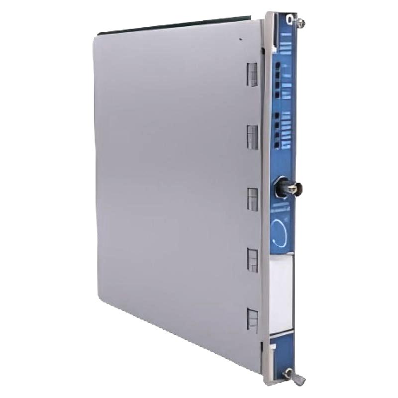 Technical Specifications
| Parameter | Specification |
|---|---|
| Manufacturer | Bently Nevada |
| Model | 3500/53-03-00 |
| Product Type | Overspeed Detection Module |
| Product Series | 3500 Machinery Protection System |
| Primary Function | Electronic overspeed detection and rotating machinery protection |
| Channel Configuration | 3 channels |
| Input Type | Tachometer pulse signal |
| Compatible Transducers | Proximity probes and magnetic pickups |
| Input Signal Range | +10.0 V to -24.0 V |
| Input Impedance | 20 kΩ |
| Maximum Input Frequency | 20 kHz |
| Transducer Power Supply | -24 VDC, up to 40 mA |
| Overspeed Detection | Supported |
| Redundant Voting | Supported |
| Voting Configuration | Three-channel overspeed protection |
| Relay Output | SPDT relay contacts |
| Recorder Output | +4–20 mA |
| Recorder Load | 0–600 Ω |
| Buffered Transducer Output | Supported |
| Buffered Output Impedance | 550 Ω |
| Output Update Rate | Approximately 100 ms |
| Front Panel Indicators | OK, TX/RX, Bypass, Test Mode, Alarm |
| Bypass Function | Supported |
| Test Mode | Supported |
| Rack Installation | Bently Nevada 3500 Rack |
| Monitor Module | 3500/53 Overspeed Detection Module |
| I/O Module | Compatible 3500/53 I/O module |
| Typical Power Consumption | 8.0 W |
| Operating Temperature | -30°C to +65°C |
| Storage Temperature | -40°C to +85°C |
| Relative Humidity | Up to 95%, non-condensing |
| Typical Applications | Steam turbines, gas turbines, compressors, generators and critical rotating machinery |
| Dimensions | 241.3 × 24.4 × 241.8 mm |
| Weight | 0.82 kg |
FAQ
1. What is the main function of the Bently Nevada 3500/53-03-00?
The Bently Nevada 3500/53-03-00 is a three-channel electronic overspeed detection module designed to protect high-speed rotating machinery. It continuously receives tachometer signals from compatible proximity probes or magnetic pickups and processes the incoming pulses to determine the rotational speed of the monitored shaft. When the measured speed reaches the configured overspeed protection limit, the system can initiate the appropriate protection response through its relay output. The module is suitable for critical equipment such as steam turbines, gas turbines, compressors, generators, pumps and other rotating machinery where excessive speed can result in serious mechanical damage. Its three-channel design also allows it to be incorporated into redundant overspeed protection systems, providing greater reliability than a single-channel speed detection arrangement.
2. What types of sensors can be used with the 3500/53-03-00?
The 3500/53-03-00 is designed to receive tachometer signals from compatible proximity probes and magnetic pickups. These sensors generate electrical pulses corresponding to the rotation of the machine shaft. Proximity probes are commonly installed near a suitable rotating target, while magnetic pickups generate pulses when a compatible metal target passes the sensing element. The selected sensor must match the electrical characteristics of the tachometer input and the requirements of the specific machinery application. During installation, technicians should verify the sensor type, signal output, installation position, sensor gap where applicable, field cable condition and signal stability. A weak or intermittent pulse signal can result in inaccurate speed measurement and may cause incorrect overspeed detection, even when the 3500/53 module itself is operating normally.
3. How does the 3500/53-03-00 detect an overspeed condition?
The module detects overspeed by monitoring the frequency of tachometer pulses generated by the rotating machine. As shaft speed increases, the frequency of the incoming pulses also increases. The 3500/53 processes these pulses and determines the corresponding rotational speed. The measured speed is then evaluated against the configured overspeed protection threshold. If the applicable overspeed condition is reached, the system can activate the appropriate protection relay output. Because an overspeed event can develop very quickly, the module is designed for rapid electronic detection. This makes it suitable for critical rotating equipment where the overspeed protection function must respond quickly enough to limit the risk of mechanical damage.
4. What is the advantage of the three-channel configuration?
The three-channel configuration allows three independent tachometer signals to be used within the overspeed protection system. This provides the foundation for a redundant protection arrangement in which multiple speed measurements can be compared before a protection action is initiated. Using multiple channels helps reduce the influence of a single failed sensor, damaged cable or defective detection channel. For critical turbine and compressor applications, this type of redundancy can improve the overall reliability of the overspeed protection system. The exact voting logic should be selected according to the machinery protection design and application requirements. Proper sensor installation and independent signal paths are also important because redundancy is most effective when each detection channel is genuinely independent.
5. What should be checked if the 3500/53-03-00 displays an incorrect speed signal?
Troubleshooting should begin with the complete tachometer signal path. First inspect the connected proximity probe or magnetic pickup for physical damage, incorrect installation or improper positioning. For proximity probes, the sensor gap and condition of the rotating target should be checked carefully. The field cable and terminal connections should then be inspected for loose connections, broken conductors, short circuits, grounding problems, moisture and electromagnetic interference. During machine operation, the sensor output should be measured to confirm that stable pulses are reaching the corresponding input channel. If the field signal is correct, check the system configuration and speed scaling parameters. Incorrect pulse-per-revolution settings can cause a consistently incorrect RPM reading, while unstable readings are more likely to be associated with sensor, wiring or signal-quality problems.
6. What do the front-panel indicators on the 3500/53-03-00 mean?
The front-panel indicators provide information about the operating condition of the overspeed detection module. The OK indicator shows the general operating status of the module. The TX/RX indicator provides information about communication activity between the module and other components in the 3500 rack. The Bypass indicator shows that a bypass condition is active, which is particularly important during maintenance because bypassing a protection function can reduce the available machinery protection level. The Test Mode indicator shows that the system is operating under a test condition. Alarm indicators provide information about associated alarm or protection states. During troubleshooting, these indicators should be considered together with the rack status, tachometer signal and system configuration rather than using one indicator alone to determine the cause of a problem.
7. How does the 4–20 mA recorder output work?
The 3500/53-03-00 provides a +4–20 mA recorder output that represents the configured rotational speed range. This analog output can be connected to an external recording, indication or control system when continuous speed information is required outside the 3500 rack. The supported recorder load is 0–600 Ω, so the receiving instrument and total cable loop resistance should remain within the specified range. During commissioning, the analog output should be checked against known machine speed values to verify that the external system is receiving the correct signal. If the external display shows an incorrect value while the 3500/53 itself indicates the correct speed, technicians should check the recorder output wiring, receiving instrument configuration and signal scaling before investigating the tachometer input.
8. What should be checked after replacing a 3500/53-03-00 module?
After replacing a 3500/53-03-00, the complete overspeed protection circuit should be inspected and tested before the machine returns to normal operation. First confirm that the replacement module has the correct three-channel configuration and is properly installed in the 3500 rack. Then check each tachometer sensor, field cable, terminal connection and incoming pulse signal. The speed scaling, overspeed setpoints, alarm parameters and relay logic should be compared with the approved machinery protection configuration. If the system uses redundant voting, each detection channel should be tested individually to verify that all channels provide valid speed information and participate correctly in the configured protection logic. The OK, TX/RX, Bypass and Test Mode indicators should also be checked. Finally, the relay output, recorder output and overspeed response should be verified according to the approved commissioning procedure to ensure that the replacement module is correctly integrated into the complete machinery protection system.
Bently Nevada 3500/53-03-00 Overspeed Detection Module is in stock. Please contact us for a quick quote and competitive pricing.
| Company Information | ||||||||
| [email protected] | ||||||||
| Mobile | +8613666084105 | |||||||
| +8613666084105 | ||||||||
| 13666084105 | ||||||||
| Add to | Room 1004, No. 62 Xiangxiu Li, Siming District, Xiamen City, Fujian Province, China | |||||||
Company Introduction
Xiamen Shengruite Trading Co., Ltd. is a company specializing in the supply of industrial PLC spare parts.
We provide high-quality PLC spare parts to customers in the global manufacturing, energy and power, chemical and other fields.
Since its establishment in 2011, after 13 years of rapid development, the cumulative global shipments have reached 223,650 pieces, with an annual output value of US$50 million.
Successfully served more than 500 customers in more than 100 countries and regions including Saudi Arabia, UAE, the United States, Europe, Africa, and Southeast Asia
Our Mission
Provide customers with the best quality PLC spare parts and the fastest delivery service to ensure that their industrial automation systems are always in the best operating condition.
We provide a 1-year warranty service, and we support returns and exchanges for any issues to ensure your rights and interests are fully protected.
We can provide detailed product images upon request, and our team can arrange warehouse photos for confirmation to ensure you have all the information you need before making a purchase.
Shipping times vary depending on your location. With the support of our 16 global warehouses, we strive to deliver orders as quickly as possible. Contact us to get an estimated delivery time for your specific location.
The minimum order quantity (MOQ) is typically one unit. However, for larger orders, please contact us for potential discounts and pricing details.
Yes, we offer competitive pricing for bulk purchases. Please reach out to our sales team with the specifics of your order to receive a custom quote.
We accept various payment methods for wholesale orders, including bank transfers (T/T), letters of credit, and other options upon agreement. For large transactions, please contact us directly for payment terms.
Yes, we offer flexible ordering options for both small and large quantities. Whether youre looking for a single unit or a large batch, we can accommodate your needs.
We occasionally offer promotional discounts for new wholesale customers. Contact us to learn more about any current offers available for first-time buyers.
If you are unsure of compatibility with your existing setup please provide your system details and our support team can verify compatibility prior to purchase.
Returns are accepted within 30 days if the product is unused, unopened, and in its original packaging. Please note that return shipping and associated costs are the buyer\\\\\\\\\\\\\\\\\\\\\\\\\\\\\\\\\\\\\\\\\\\\\\\\\\\\\\\\\\\\\\\\\\\\\\\\\\\\\\\\\\\\\\\\\\\\\\\\\\\\\\\\\\\\\\\\\\\\\\\\\\\\\\\\\\\\\\\\\\\\\\\\\\\\\\\\\\\\\\\\\\\\\\\\\\\\\\\\\\\\\\\\\\\\\\\\\\\\\\\\\\\\\\\\\\\\\\\\\\\\\\\\\\\\\\\\\\\\\\\\\\\\\\\\\\\\\\\\\\\\\\\\\\\\\\\\\\\\\\\\\\\\\\\\\\\\\\\\\\\\\\\\\\\\\\\\\\\\\\\\\\\\\\\\\\\\\\\\\\\\\\\\\\\\\\\\\\\\\\\\\\\\\\\\\\\\\\\\\\\\\\\\\\\\\\\\\\\\\\\\\\\\\\\\\\\\\\\\\\\\\\\\\\\\\\\\\\\\\\\\\\\\\\\\\\\\\\\\\\\\\\\\\\\\\\\\\\\\\\\\\\\\\\\\\\\\\\\\\\\\\\\\\\\\\\\\\\\\\\\\\\\\\\\\\\\\\\\\\\\\\\\\\\\\\\\\\\\\\\\\\\\\\\\\\\\\\\\\\\\\\\\\\\\\\\\\\\\\\\\\\\\\\\\\\\\\\\\\\\\\\\\\\\\\\\\\\\\\\\\\\\\\\\\\\\\\\\\\\\\\\\\\\\\\\\\\\\\\\\\\\\\\\\\\\\\\\\\\\\\\\\\\\\\\\\\\\\\\\\\\\\\\\\\\\\\\\\\\\\\\\\\\\\\\\\\\\\\\\\\\\\\\\\\\\\\\\\\\\\\\\\\\\\\\\\\\\\\\\\\\\\\\\\\\\\\\\\\\\\\\\\\\\\\\\\\\\\\\\\\\\\\\\\\\\\\\\\\\\\\\\\\\\\\\\\\\\\\\\\\\\\\\\\\\\\\\\\\\\\\\\\\\\\\\\\\\\\\\\\\\\\\\\\\\\\\\\\\\\\\\\\\\\\\\\\\\\\\\\\\\\\\\\\\\\\\\\\\\\\\\\\\\\\\\\\\\\\\\\\\\\\\\\\\\\\\\\\\\\\\\\\\\\\\\\\\\\\\\\\\\\\\\\\\\\\\\\\\\\\\\\\\\\\\\\\\\\\\\\\\\\\\\\\\\\\\\\\\\\\\\\\\\\\\\\\\\\\\\\\\\\\\\\\\\\\\\\\\\\\\\\\\\\\\\\\\\\\\\\\\\\\\\\\\\\\\\\\\\\\\\\\\\\\\\\\\\\\\\\\\\\\\\\\\\\\\\\\\\\\\\\\\\\\\\\\\\\\\\\\\\\\\\\\\\\\\\\\\\\\\\\\\\\\\\\\\\\\\\\\\\\\\\\\\\\\\\\\\\\\\\\\\\\\\\\\\\\\\\\\\\\\\\\\\\\\\\\\\\\\\\\\\\\\\\\\\\\\\\\\\\\\\\\\\\\\\\\\\\\\\\\\\\\\\\\\\\\\\\\\\\\\\\\\\\\\\\\\\\\\\\\\\\\\\\\\\\\\\\\\\\\\\\\\\\\\\\\\\\\\\\\\\\\\\\\\\\\\\\\\\\\\\\\\\\\\\\\\\\\\\\\\\\\\\\\\\\\\\\\\\\\\\\\\\\\\\\\\\\\\\\\\\\\\\\\\\\\\\\\\\\\\\\\\\\\\\\\\\\\\\\\\\\\\\\\\\\\\\\\\\\\\\\\\\\\\\\\\\\\\\\\\\\\\\\\\\\\\\\\\\\\\\\\\\\\\\\\\\\\\\\\\\\\\\\\\\\\\\\\\\\\\\\\\\\\\\\\\\\\\\\\\\\\\\\\\\\\\\\\\\\\\\\\\\\\\\\\\\\\\\\\\\\\\\\\\\\\\\\\\\\\\\\\\\\\\\\\\\\\\\\\\\\\\\\\\\\\\\\\\\\\\\\\\\\\\\\\\\\\\\\\\\\\\\\\\\\\\\\\\\\\\\\\\\\\\\\\\\\\\\\\\\\\\\\\\\\\\\\\\\\\\\\\\\\\\\\\\\\\\\\\\\\\\\\\\\\\\\\\\\\\\\\\\\\\\\\\\\\\\\\\\\\\\\\\\\\\\\\\\\\\\\\\\\\\\\\\\\\\\\\\\\\\\\\\\\\\\\\\\\\\\\\\\\\\\\\\\\\\\\\\\\\\\\\\\\\\\\\\\\\\\\\\\\’s responsibility.
Yes, we offer technical support for the installation and integration of our products. Our team can assist with setup, configuration, and troubleshooting to ensure a smooth installation.